THIS AUTOMOTIVE LIFT WAS A GROUP PROJECT THAT INCLUDED MYSELF AND FIVE OTHER CLASSMATES. THIS WAS A GREAT LEARNING EXPERIENCE, AS WE HAD TO WORK TOGETHER TO ACHIEVE OUR GOALS WHILE MEETING OUTSIDE OF CLASS TIME TO WORK TOGETHER, WITH THE ADDED CHALLENGE OF WORKING REMOTELY DUE TO COVID RESTRICTIONS. THE PROJECT DEMONSTRATES ADVANCED WORKBENCHES IN CATIA, SUCH AS; KINEMATICS, PRISMATIC MACHINING, SHEET METAL & KNOWLEDGEWARE. I WAS RESPONSIBLE FOR BUILDING THE TELESCOPING LEGS USING KNOWLEDGEWARE AND KINEMATICS.
This set of photos shows two different surfacing student projects.
The first 2 photos show a motorcycle seat designed by me to fit a friends motorcycle. The project proved more difficult than I had anticipated, but in the end, it is just what I was going for.
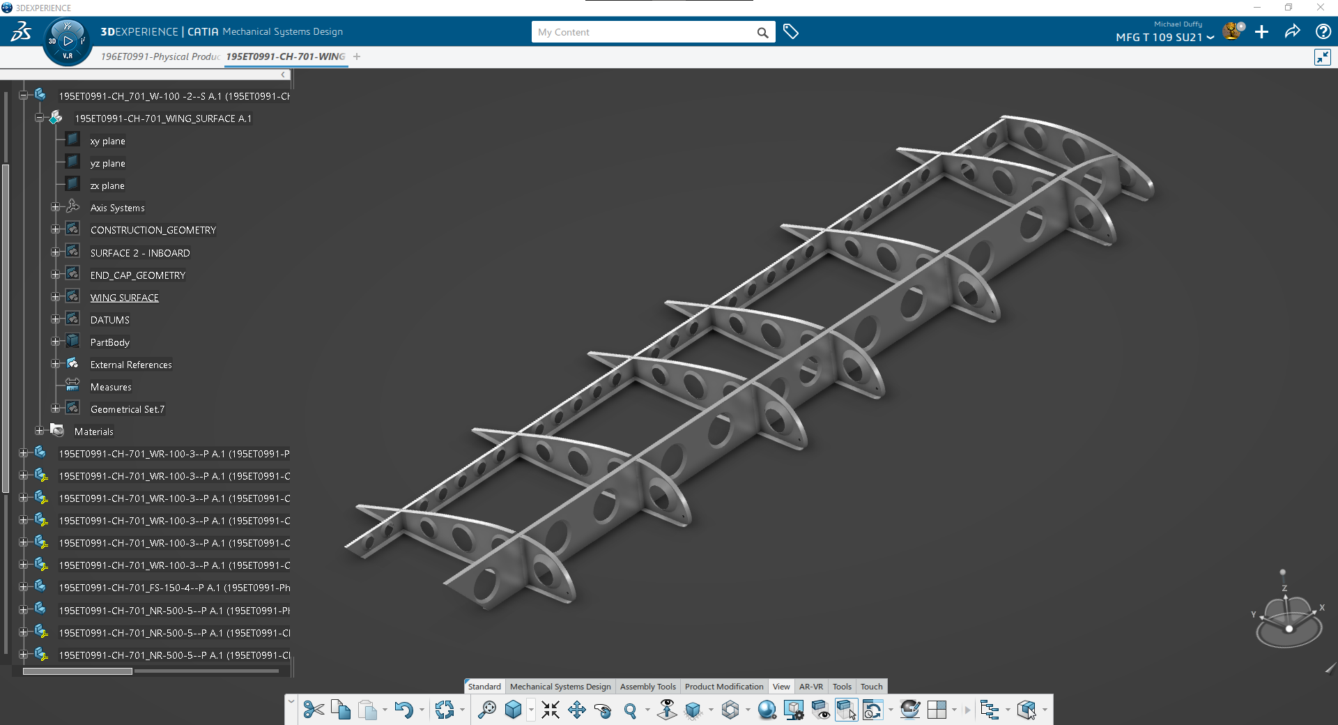
The second set of screenshots displays a large student project. The assignment was to make a wing. I wanted a real wing, so I found a set of plans for a Zenith CH-701 kit-plane online to use to reverse engineer the wing. Using surfacing features Fill, and Sweep to create the ribs, spars and hole flanges. In creating this, I learned a valuable lesson after getting some advice from my instructor. It is better to create the outer skin surface first. Then create the ribs and spars to contact it, than to create the structure first, then attempt to skin it.
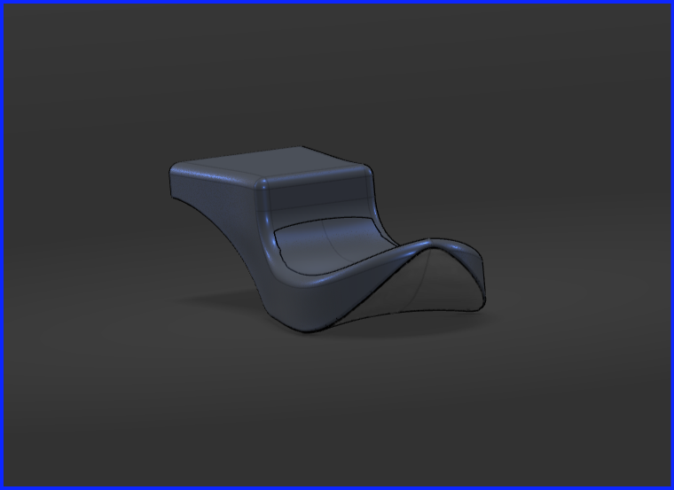
Motorcycle Seat Assembly - Alt. View - CATIA 3D Exp. Consisting of a Bottom Plate, Foam Pad, & Leather Covering
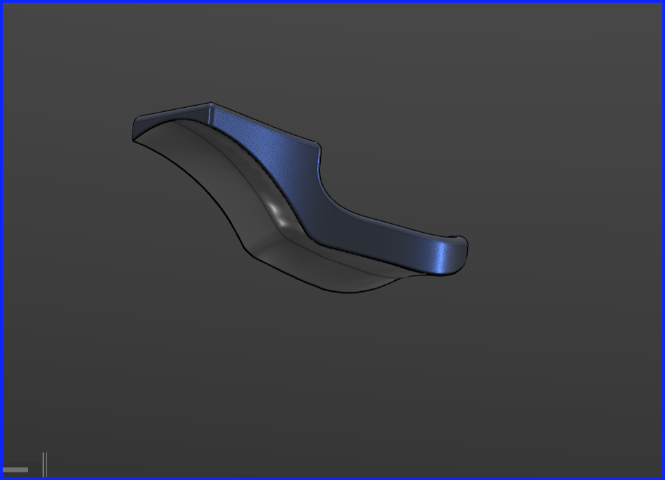
Motorcycle Seat Assembly - CATIA 3D Exp - Different view showing the Bottom Plate with Leather Cover wrapped around bottom edges.
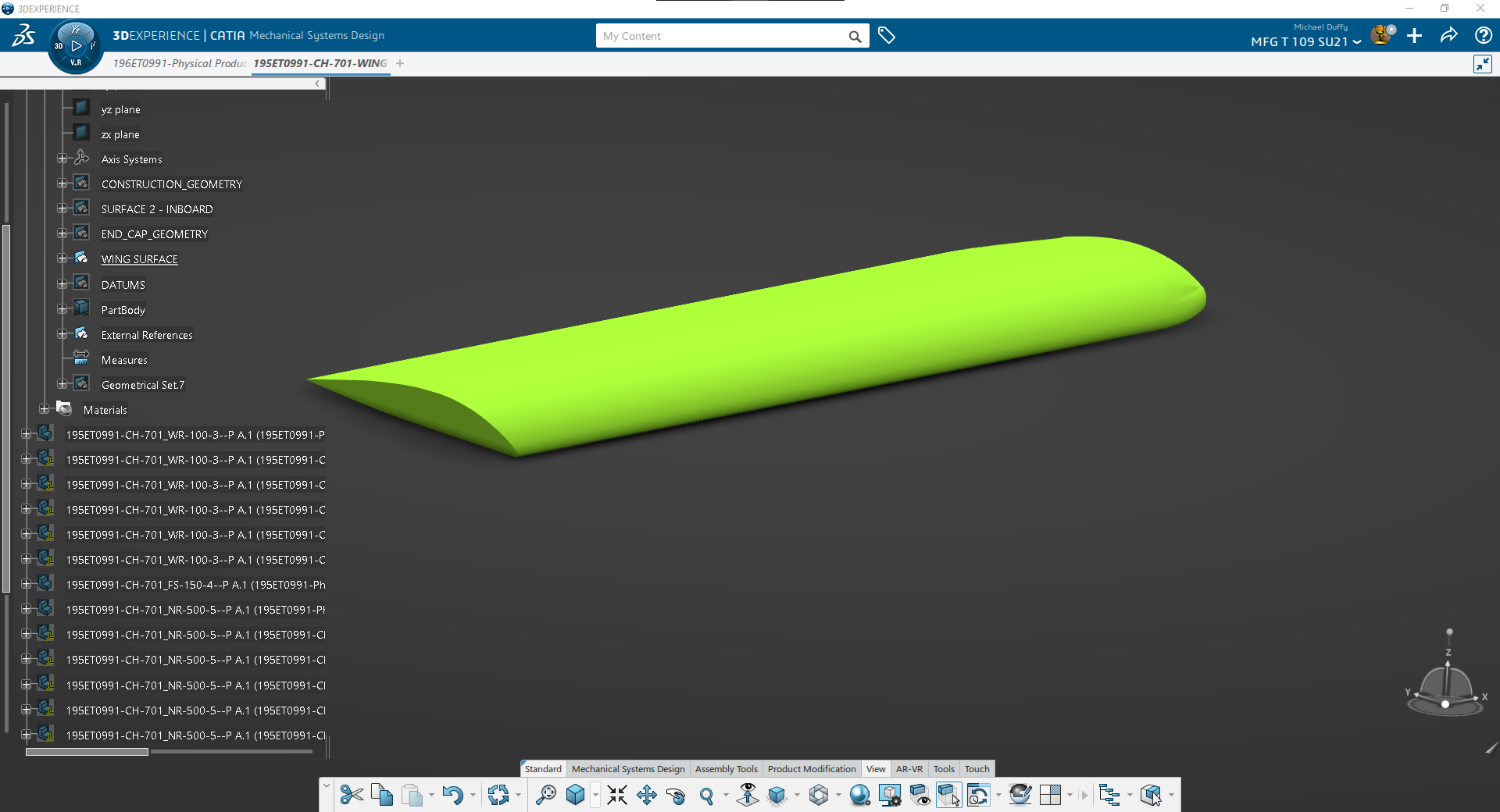
Outer wing surface for CH-701 Wing created with Sweep tool in the Generative Shape Design Workbench.
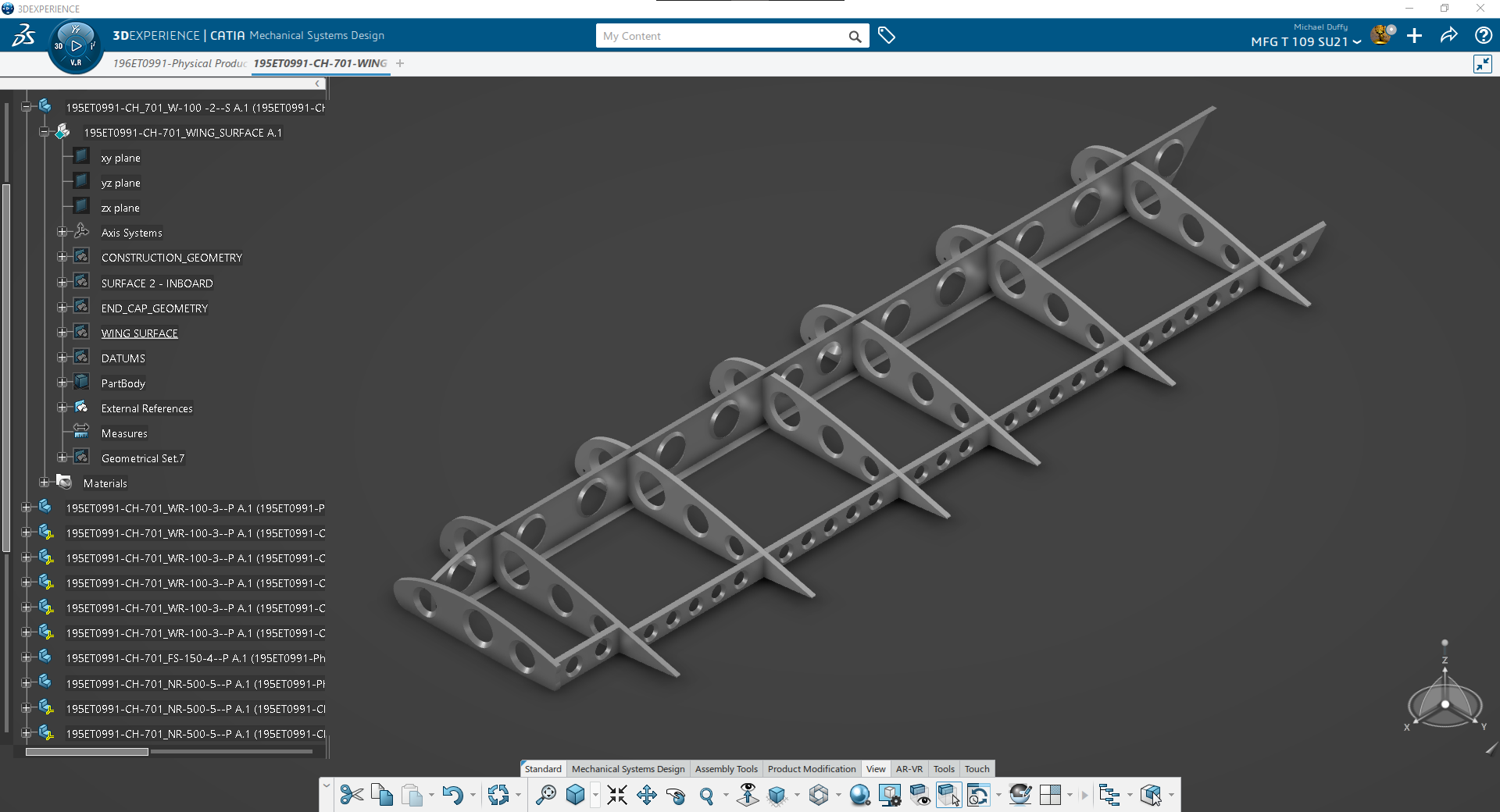
CH-701 Wing Structure Assembly. Showing Ribs and Spars, with flanged holes.
Isometric view of Wing Assembly Structure.
The following set of photos documents some of the steps involved in this Capstone project. This was a Group Project with team members from all 5 vocational programs. We were tasked with designing and creating a prototype for National Manufacturing Day tours with youths. The goal was create something fun and interesting, as well as useful to a teen, that could be completed by them in a 30 minute period, without using any power tools or potentially hazardous equipment. The project had a budget of $3000 for 500 units.
Our group began by brainstorming ideas. Voting to decide on a project idea, and dividing up responsibilities by ability and training program. We decided on a video game controller stand, that can also be used for phones or tablets. I then took the design sketch decided upon, and created a 3d model. After doing a cost analysis, the project was over budget due to the cost of the metal. The team then went back to the drawing board and redesigned the stand to reduce cost. The metal and other parts were acquired and the metal was cut-out on the water-jet at EvCC AMTEC. We then designed and created stickers and assembled 6 prototypes that will be used in the near future for National Manufacturing Day.
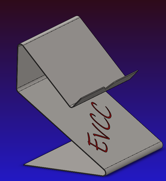
Original Controller Stand Design
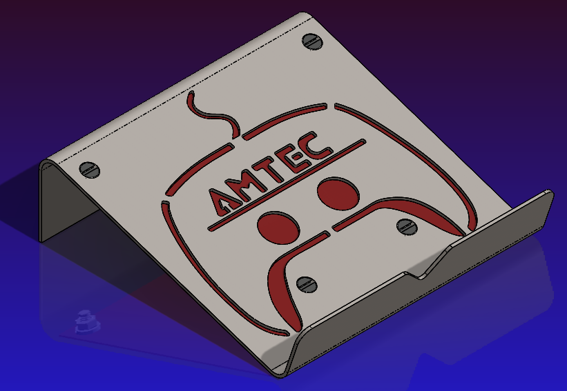
New Design that moved forward to prototyping
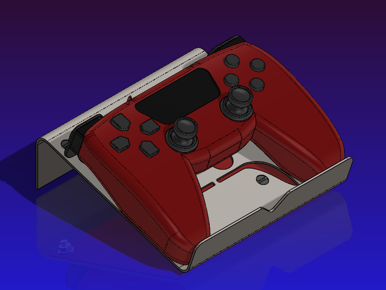
New Design with Controller Mock-up for EvCC Staff Review and Approval
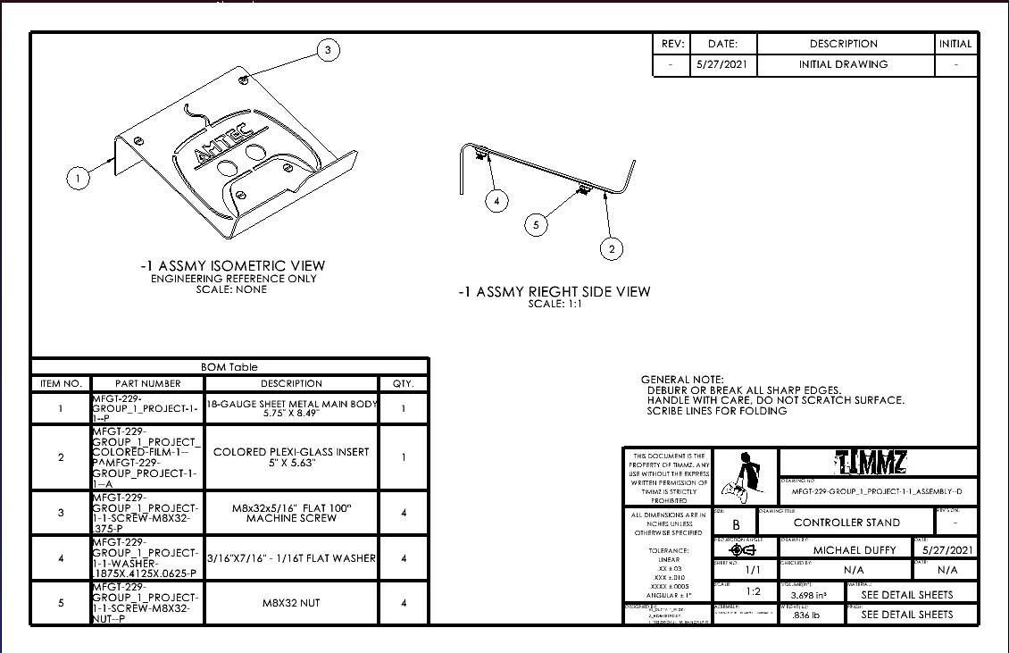
Assembly Drawing for Stand
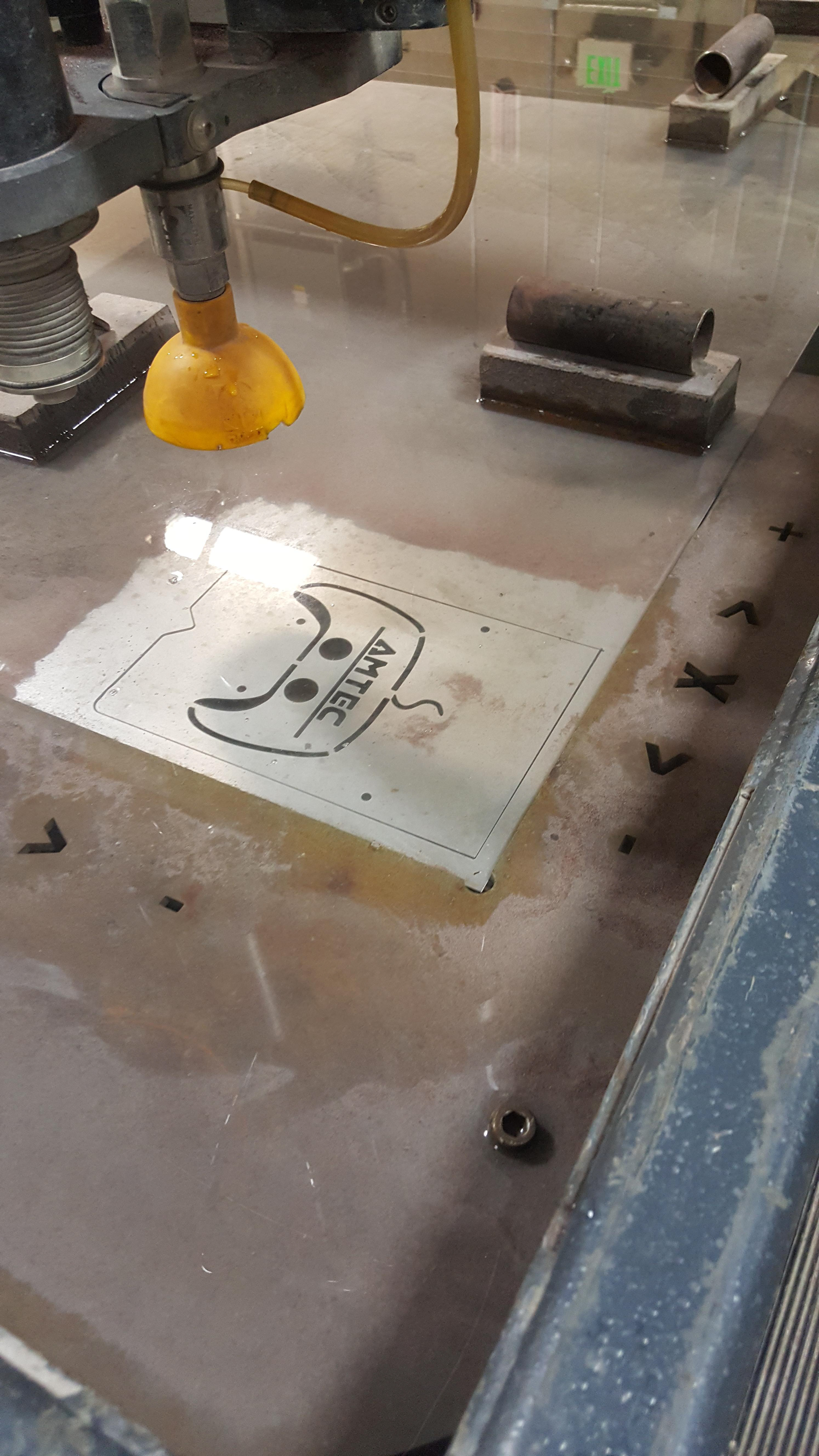
Photo of First Prototype on Water-Jet Cutting Table
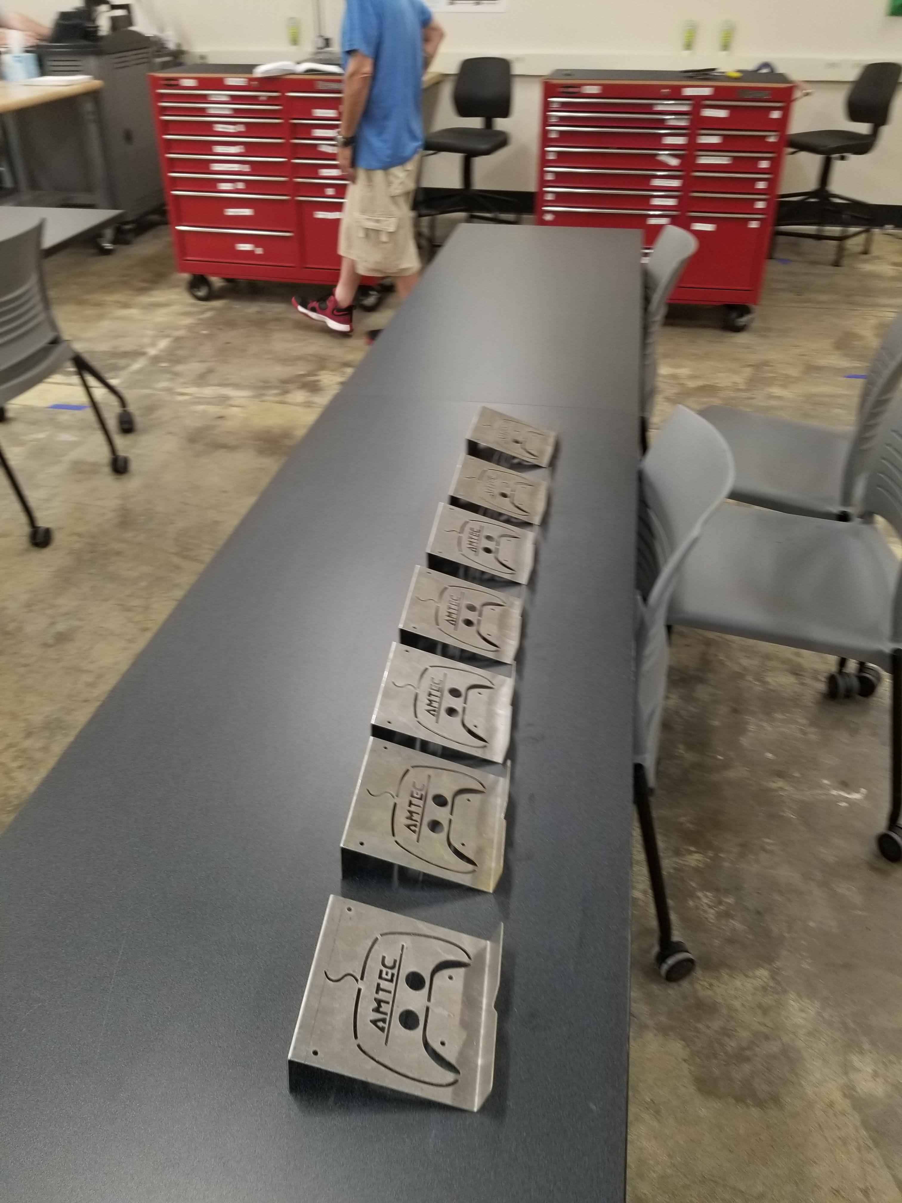
Line of Prototypes after Bending
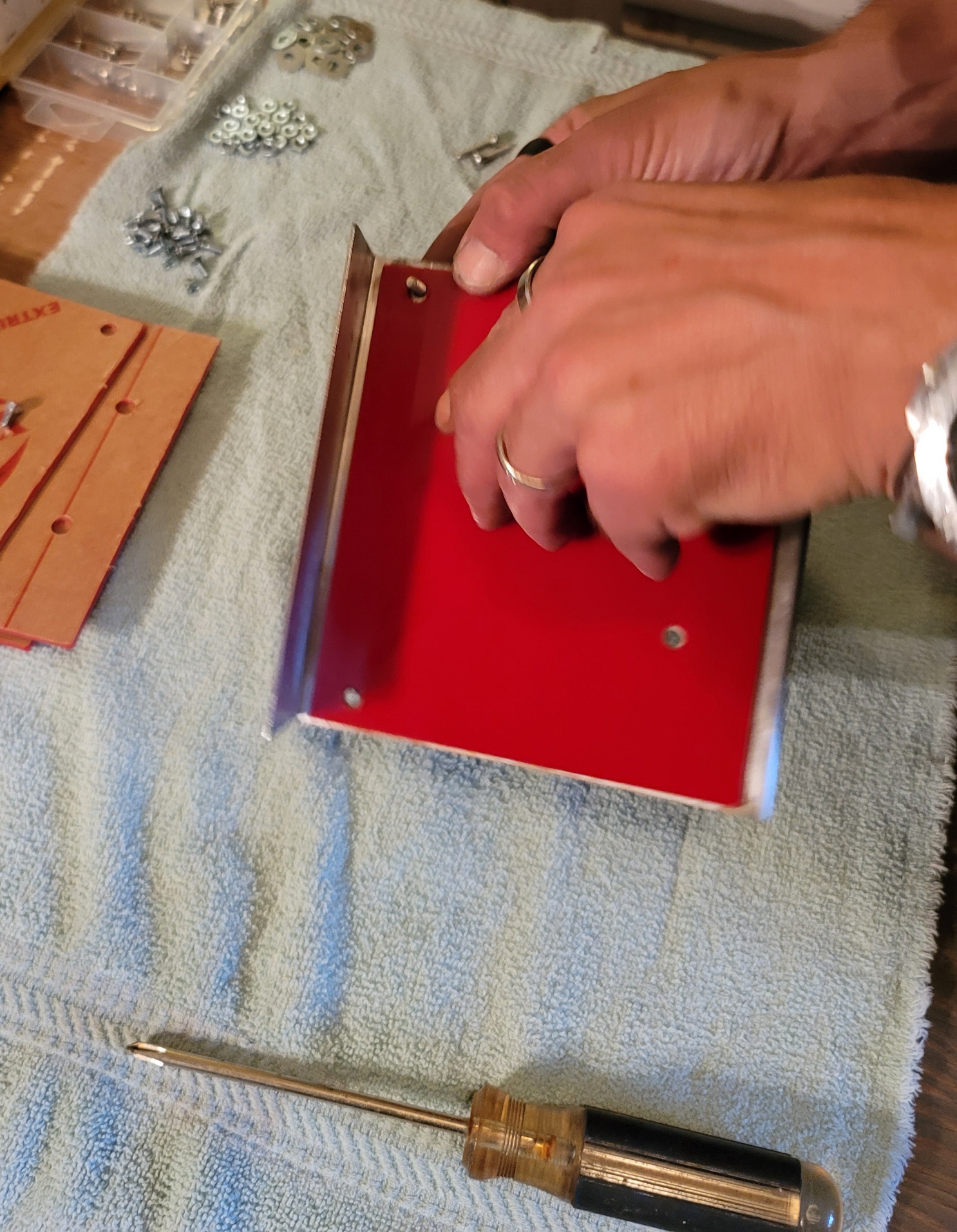
Plexiglass Backing being installed
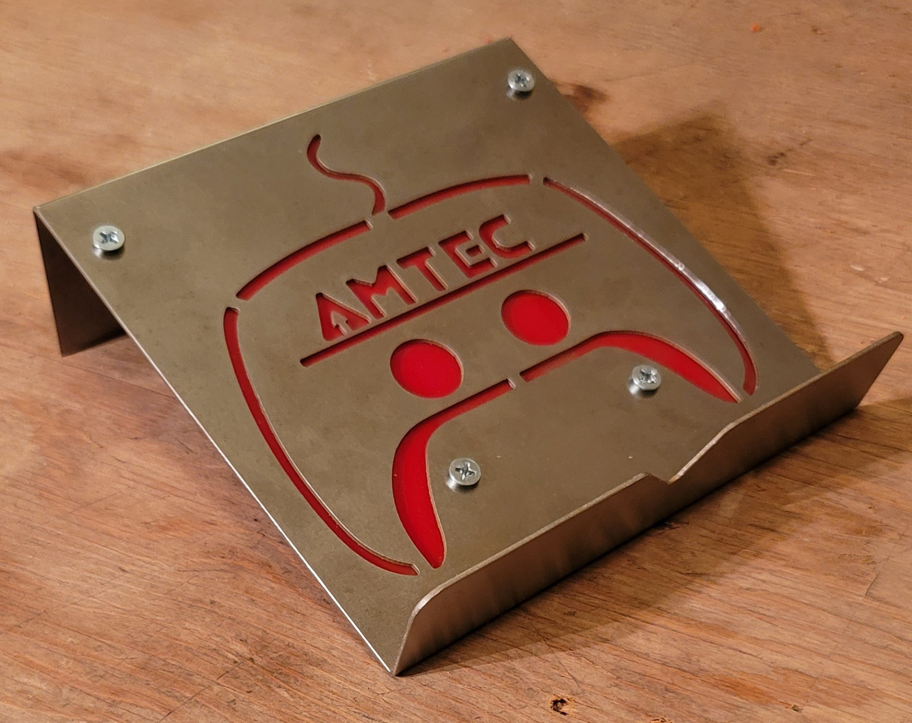
First Prototype
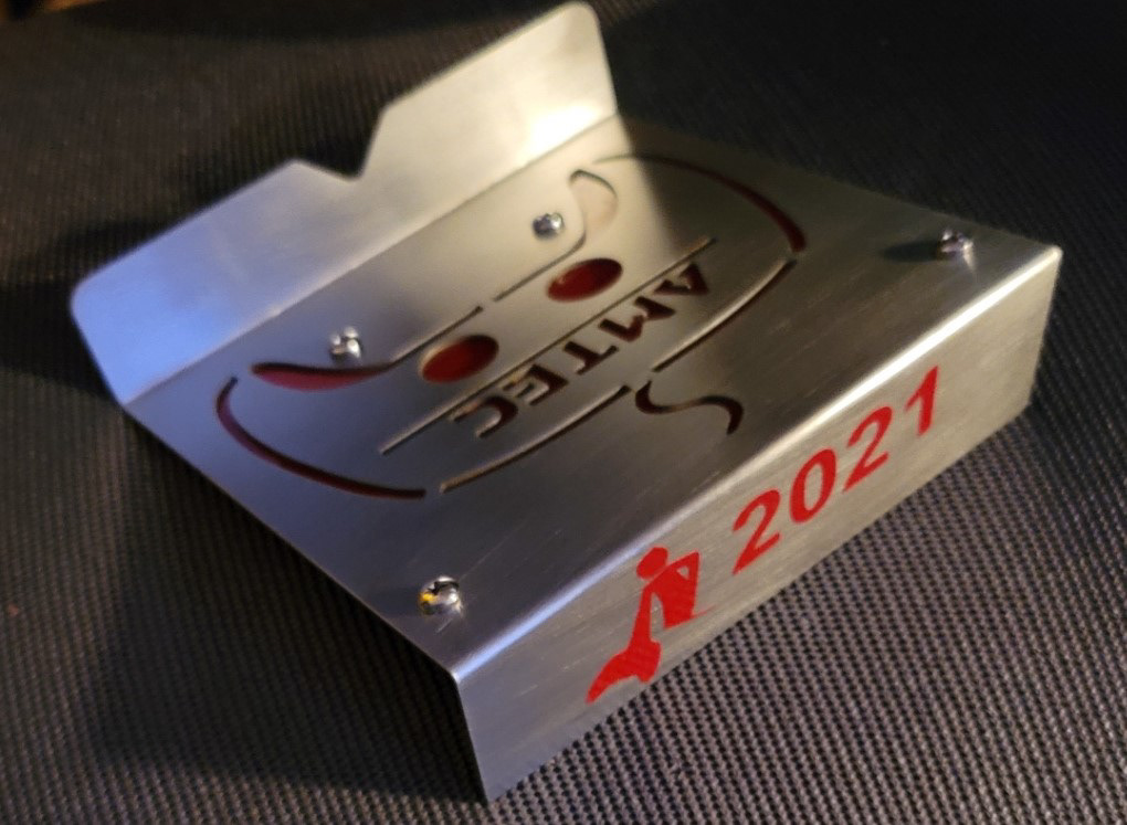
Finished Prototype with Sticker
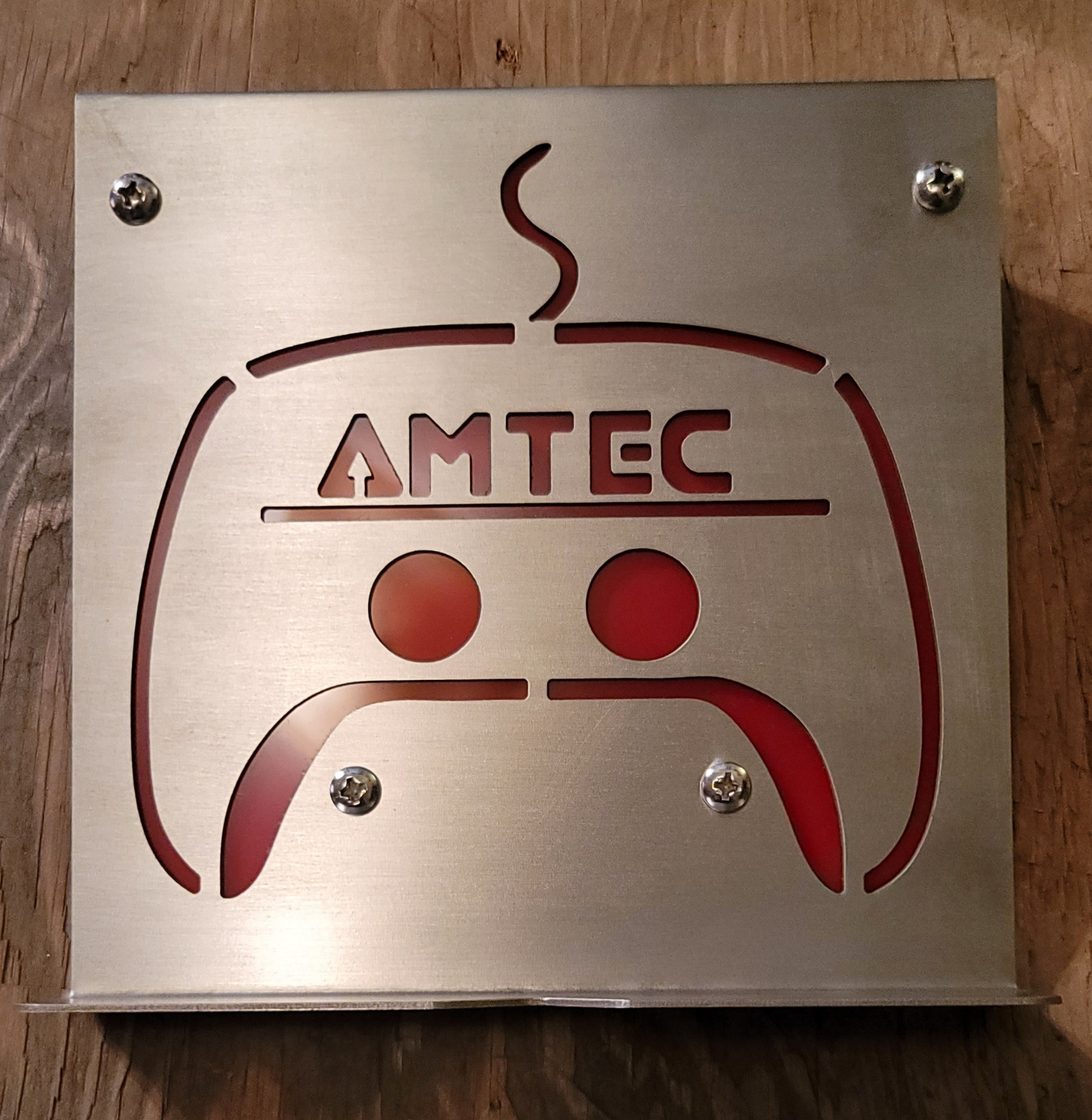
Finished Product
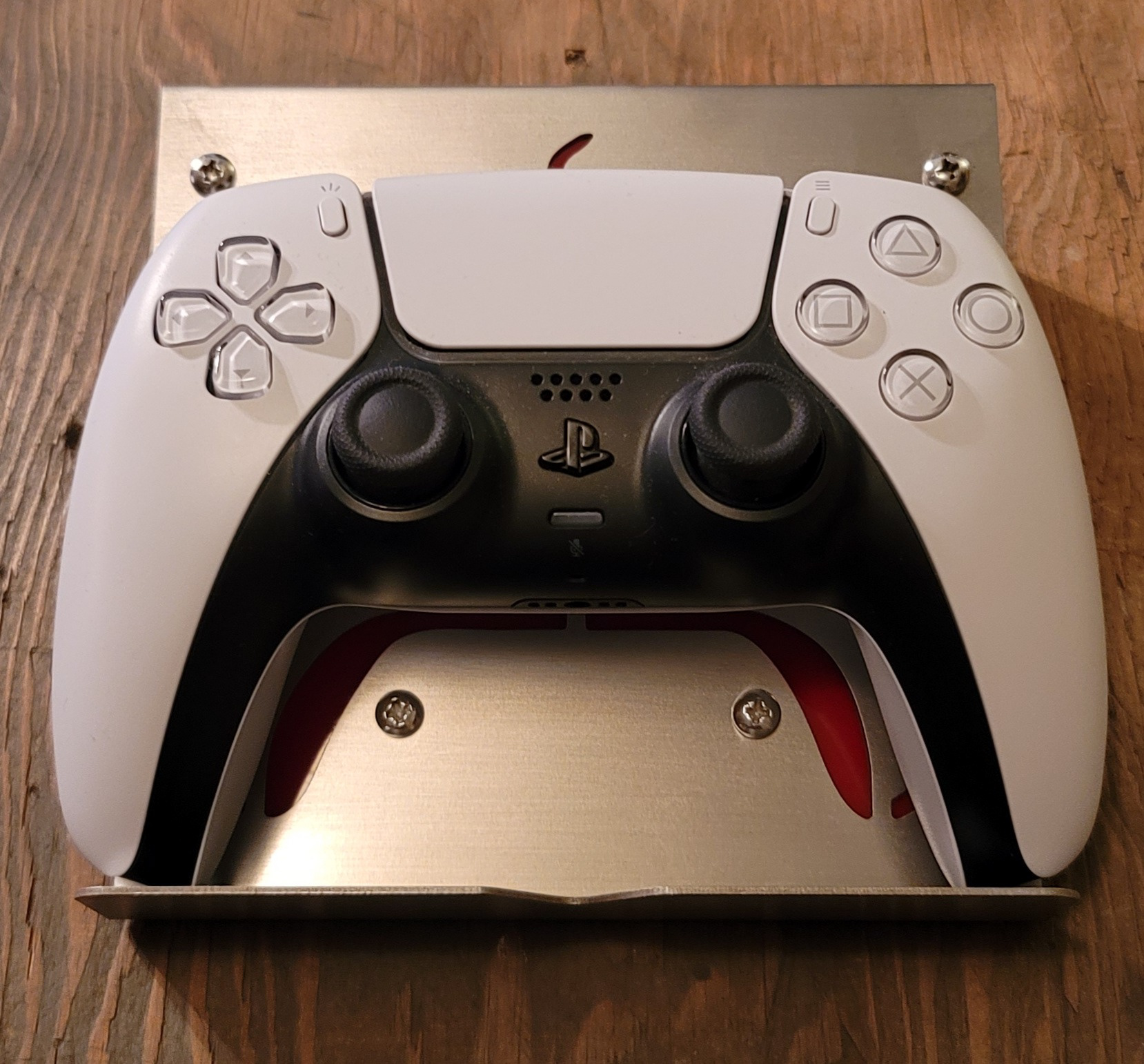
Displayed with Game Controller
These are photos of some other projects that I have created.
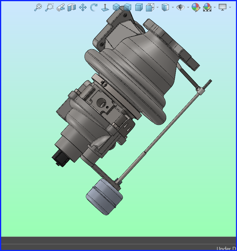
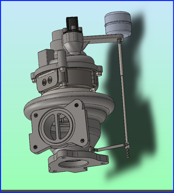
The first two pictures show a Turbocharger Diverter Valve that I modeled in CATIA 3D Experience
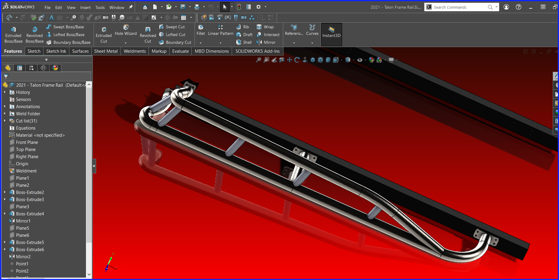
A "Tree Kicker" and a Roll Cage Designed for a friends Honda Talon UTV
The final two images show a new air vent designed for my 2012 R60S MINI Cooper Countryman that will house a Gauge in the center.
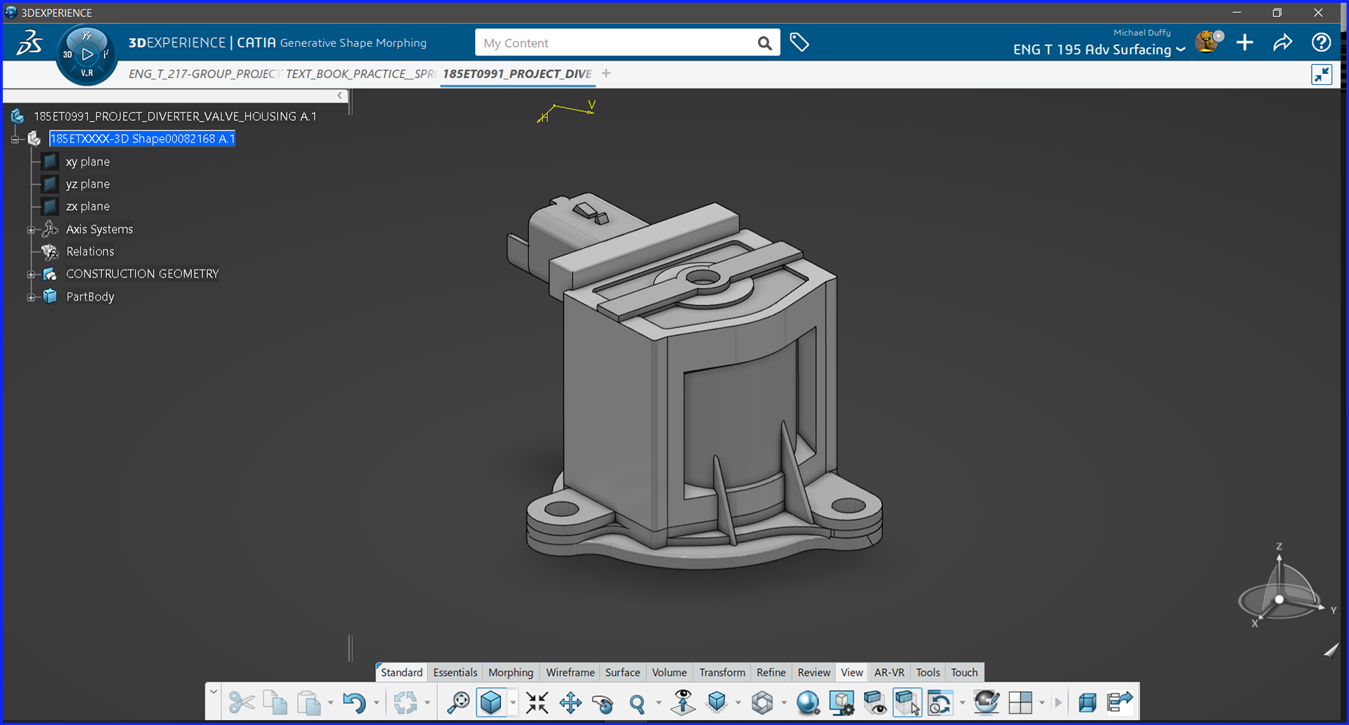
Model of Turbocharger Diverter Valve - CATIA 3D Exp
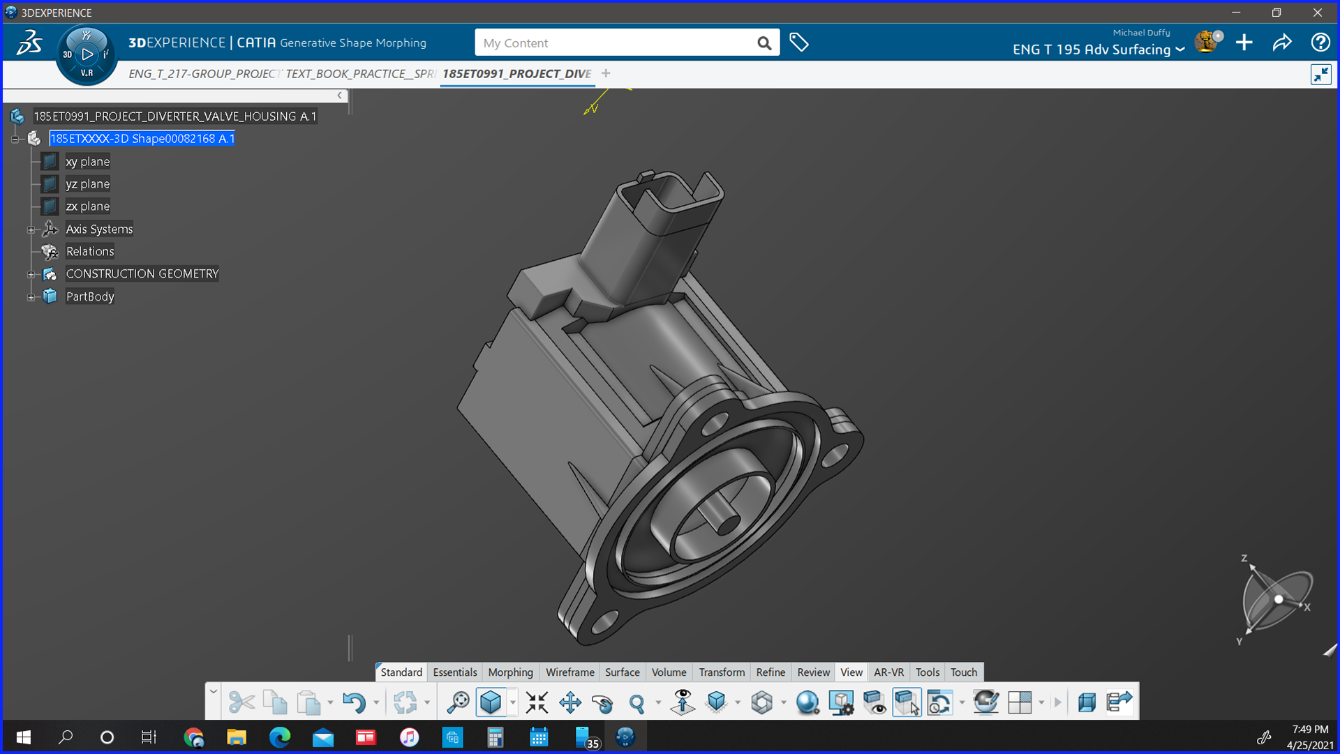
Diverter Valve Alt. View - CATIA 3D Exp
Tree Kickers for Honda Talon - Solidworks
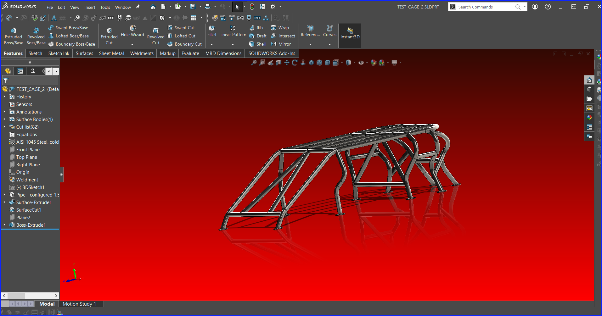
Dune Buggy Roll-Cage - Solidworks
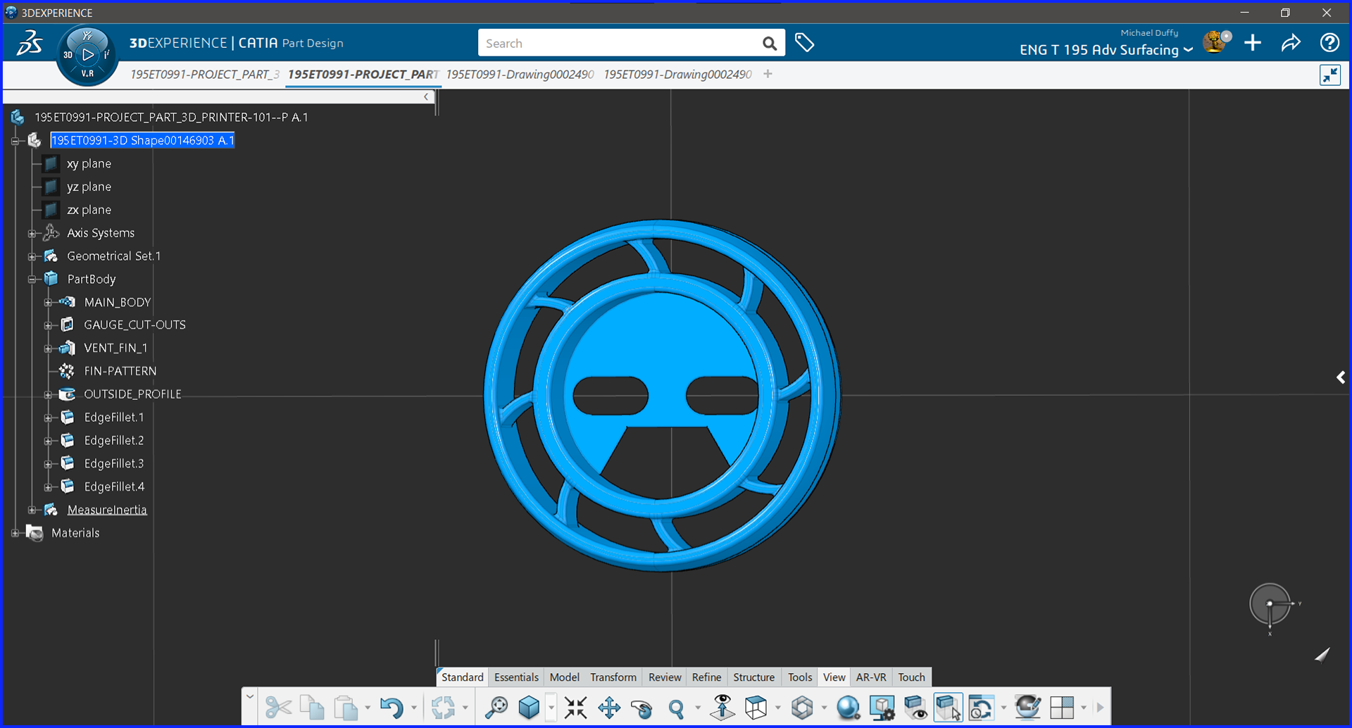
Vent Mount Gauge Pod For 2012 MINI R60S - CATIA 3D Exp
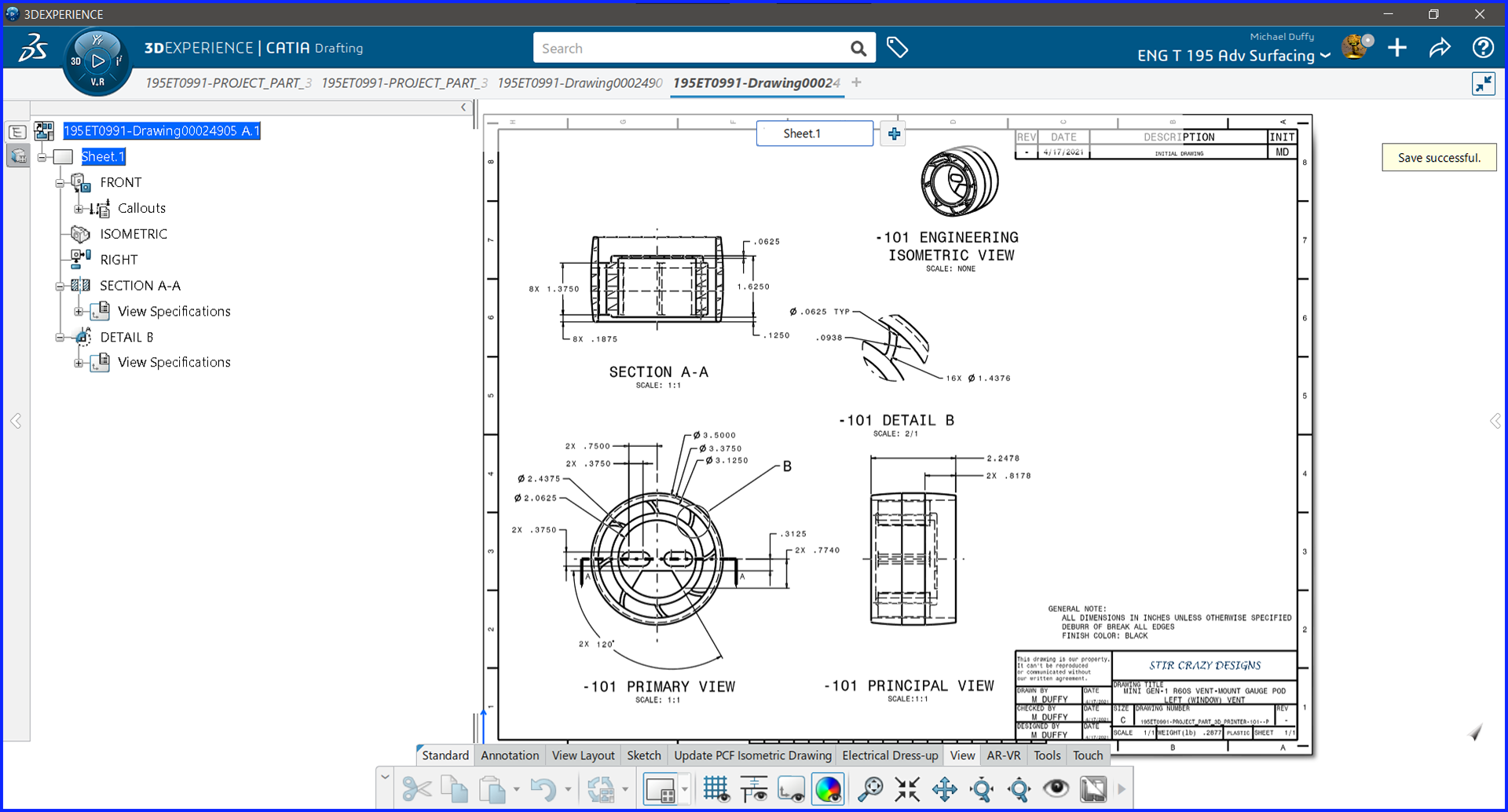
Gauge Pod Drawing - CATIA 3D Exp
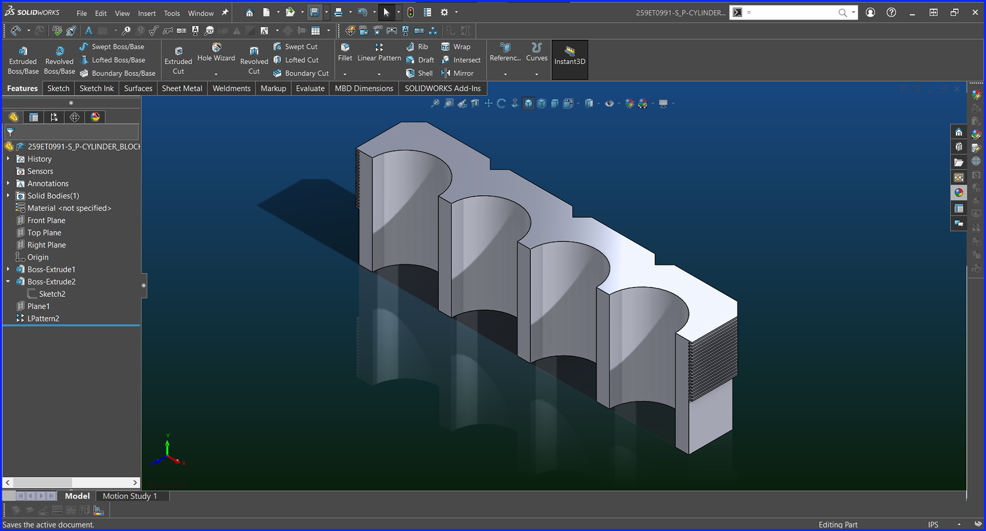
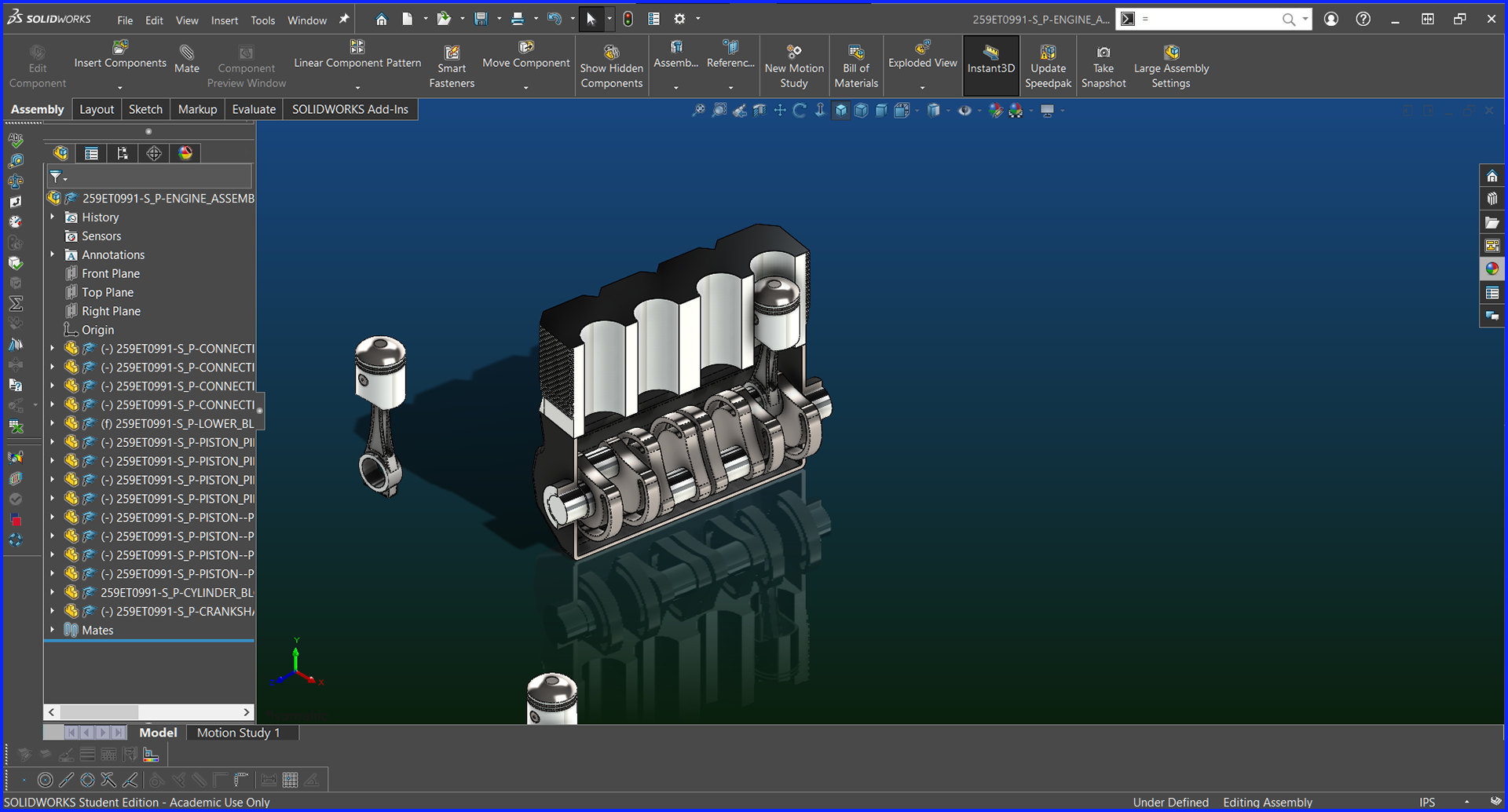
This section shows an Engine created in Solidworks for a student project. Using kinematics I was able to animate the motion of the Engine as seen on the front page
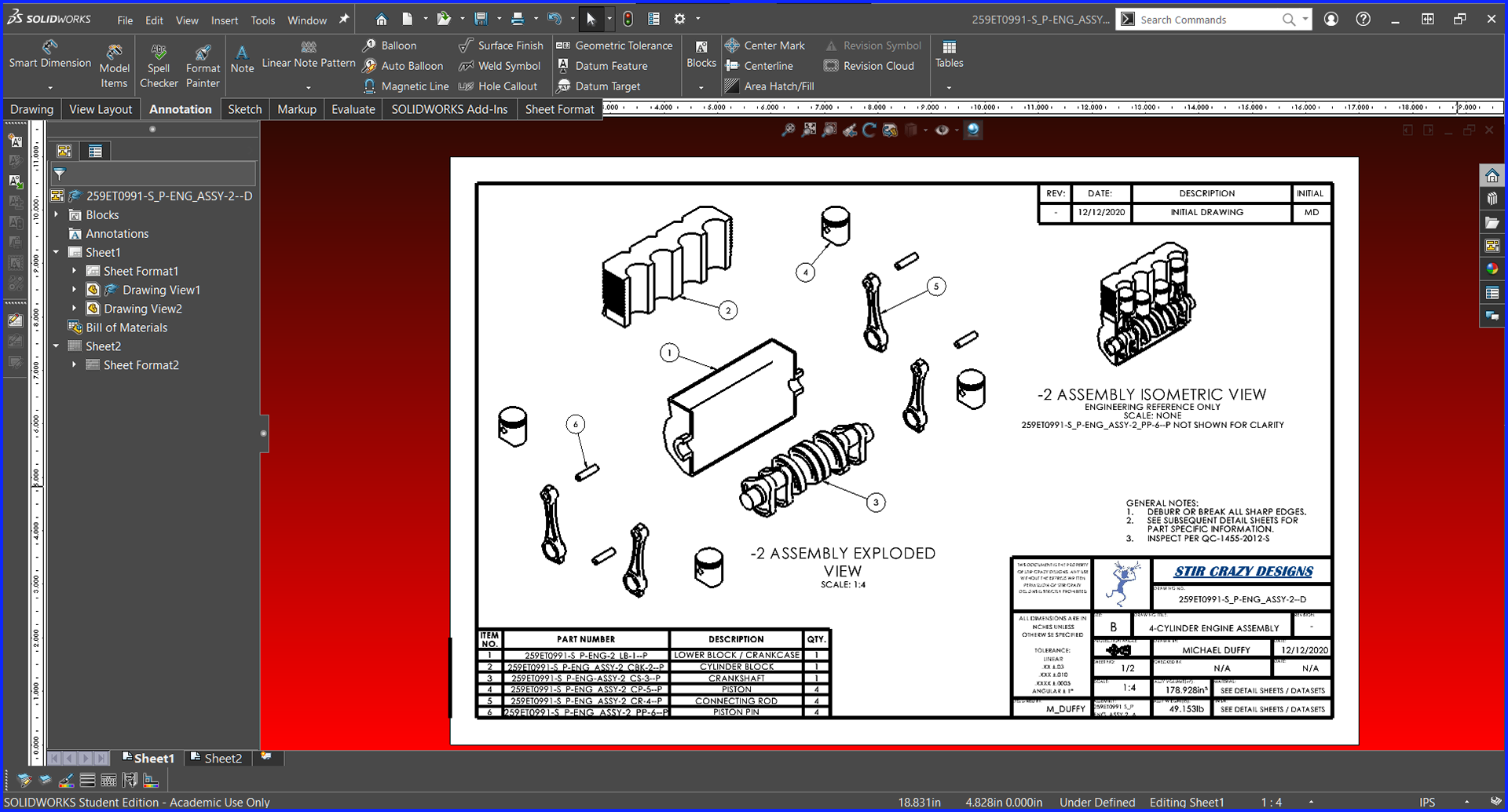
Assembly Drawing Exploded View with Bill of Materials
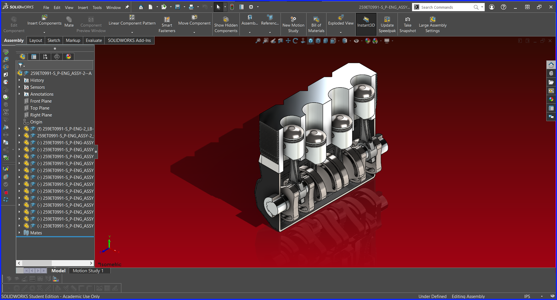
The Completed Engine Assembly
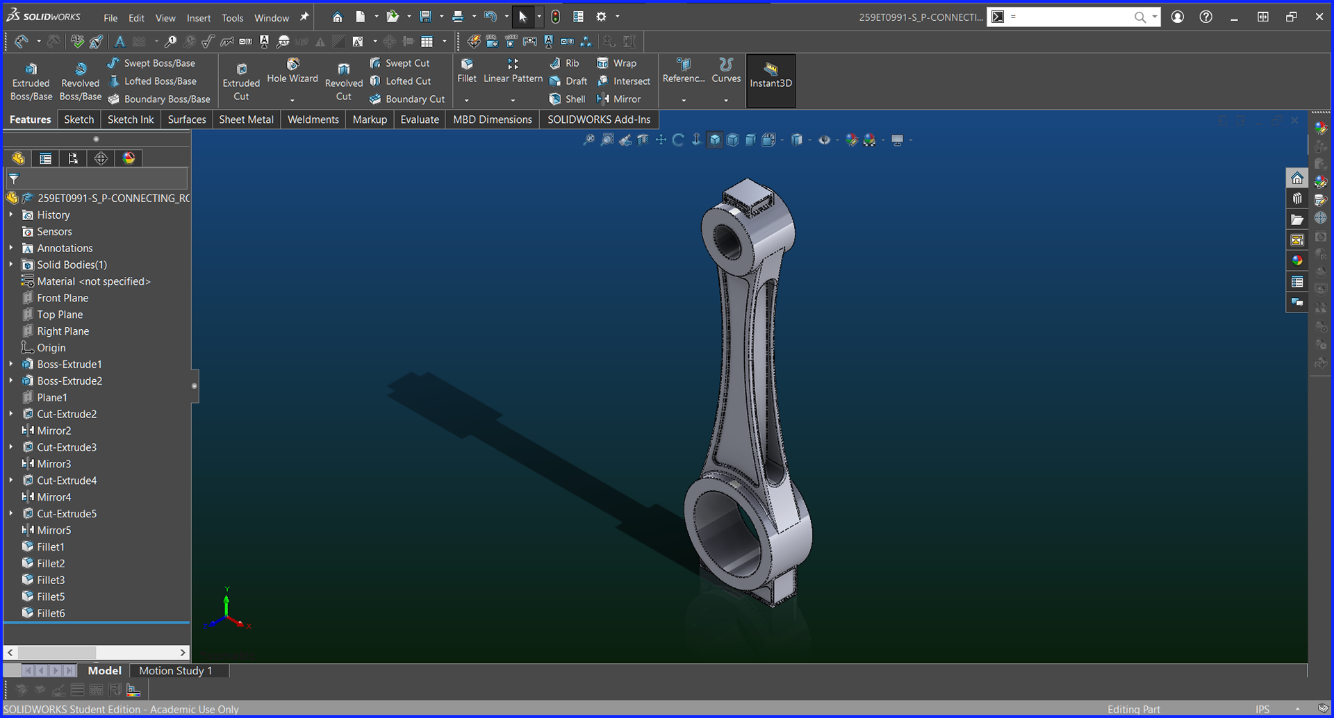
Connecting Rod with complex shape and multiple complex pockets
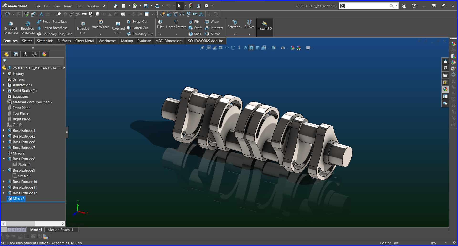
Crankshaft that was made for the Engine. Note the offsets.
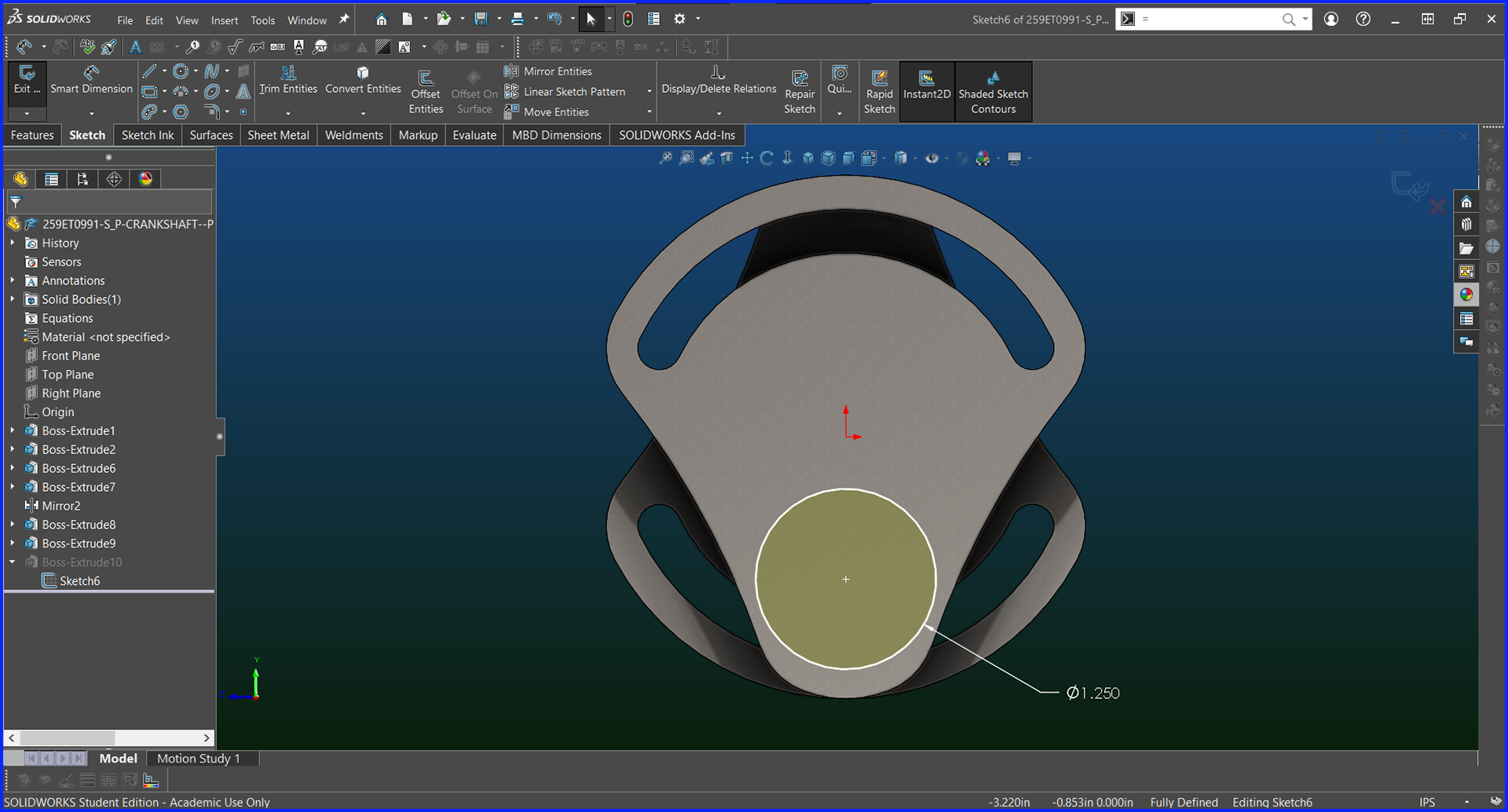
Crankshaft Sketch
Cylinder Head Half
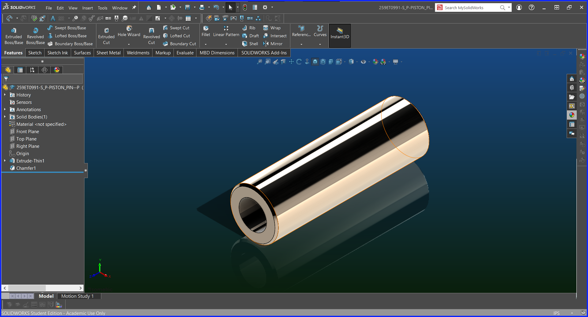
Piston Pin
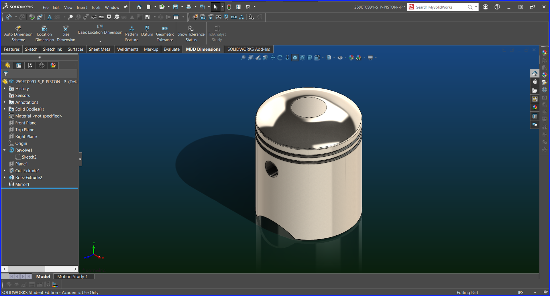
Piston
Crankcase with Cylidner Head
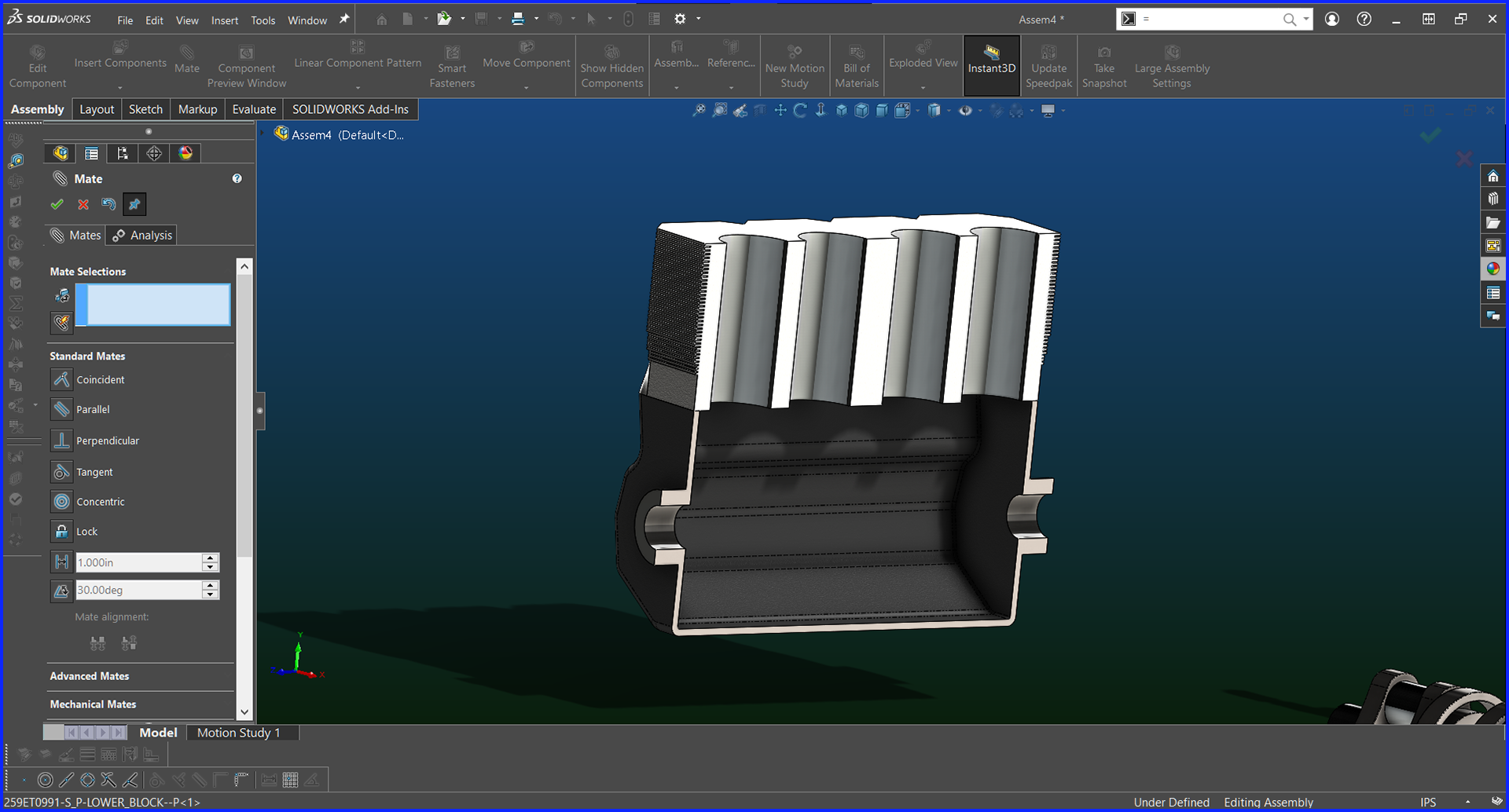
Adding the Pistons
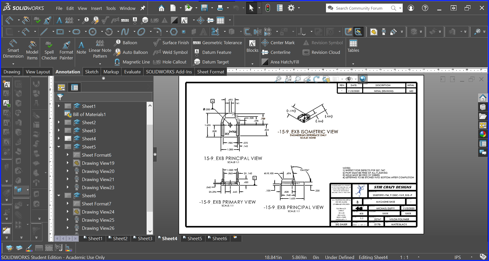
This is a Student Project that I created in Solidworks. It is a Magazine which has many complex shapes, inset lettering, and a complicated spring involved
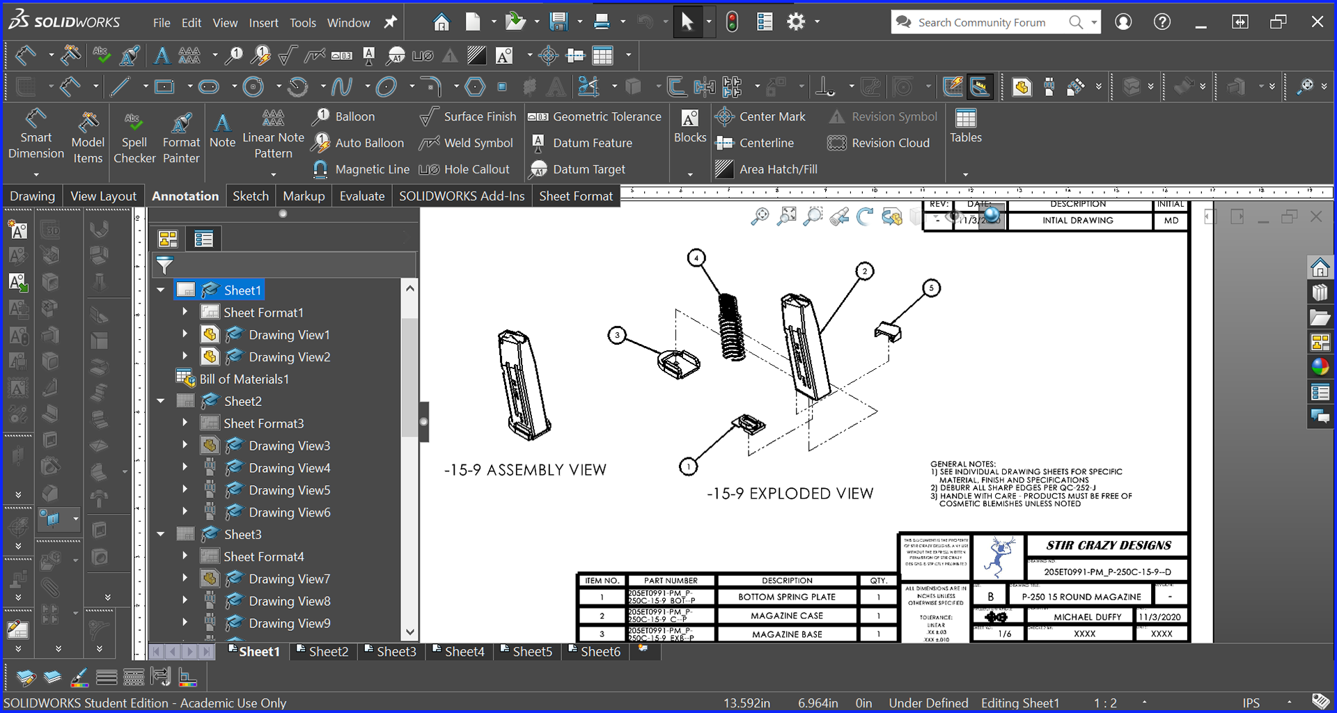
Assembly Drawing with Exploded View
Spring Base Drawing
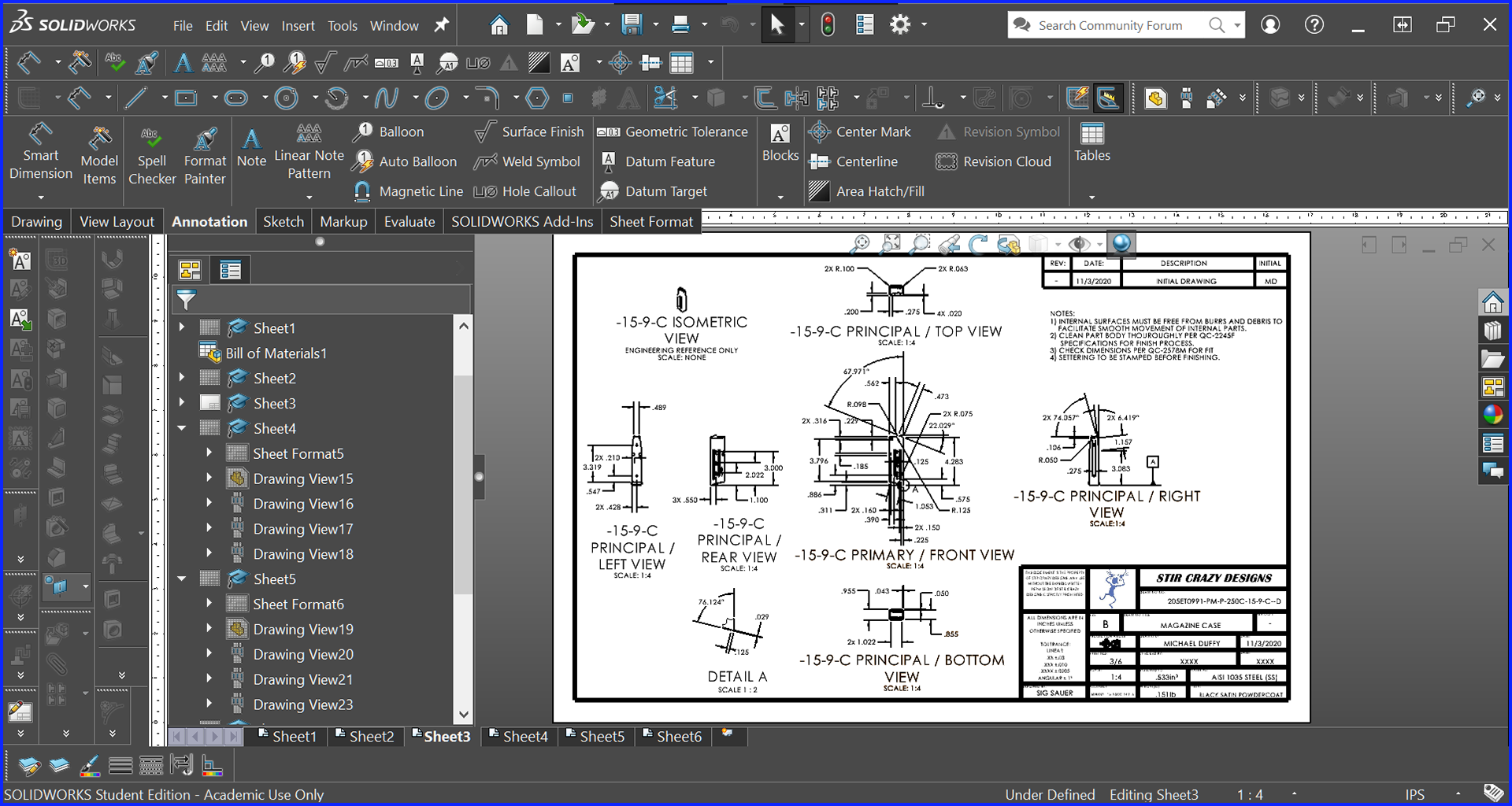
Magazine Shell Drawing
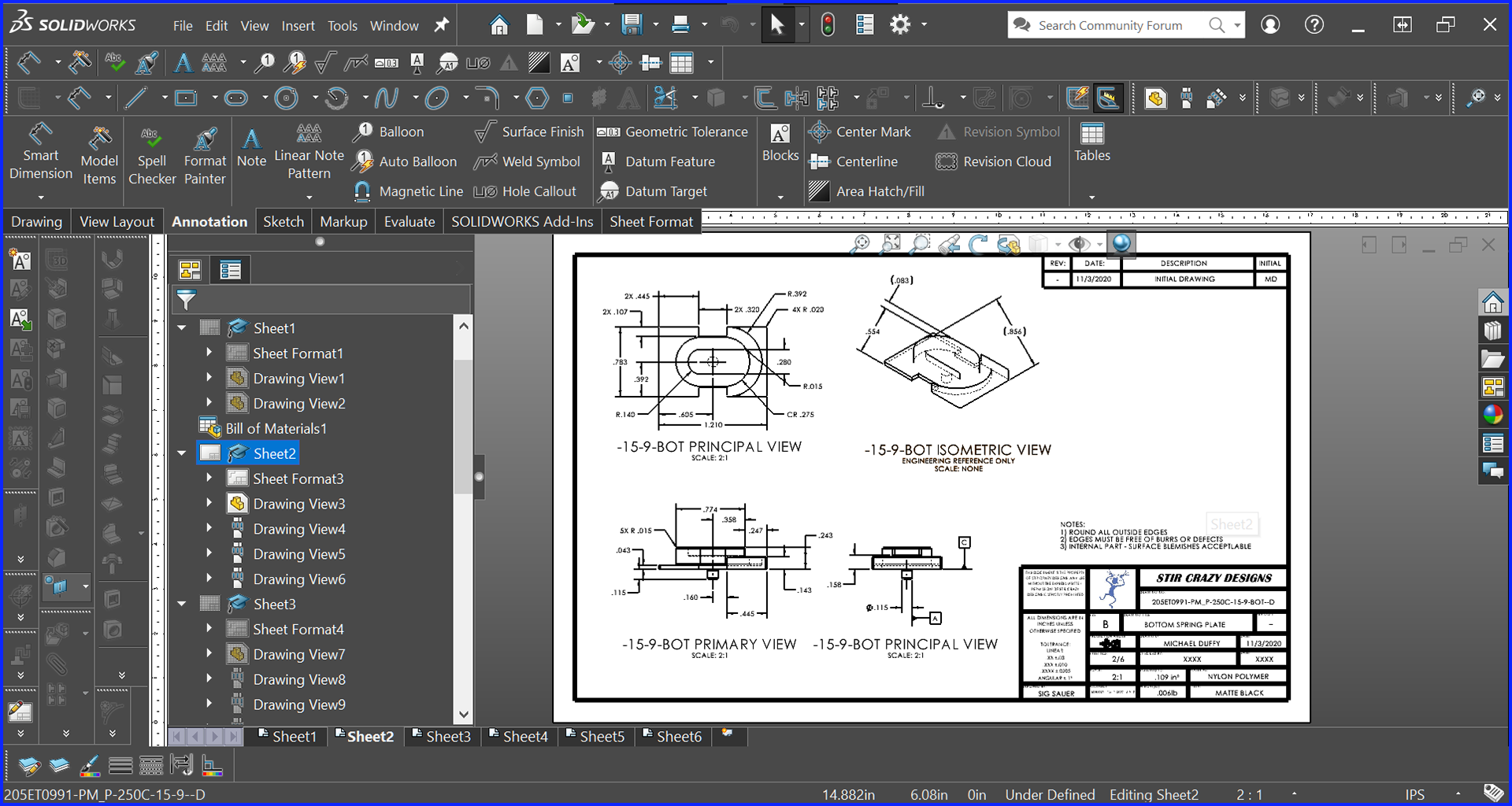
Base Plate Drawing
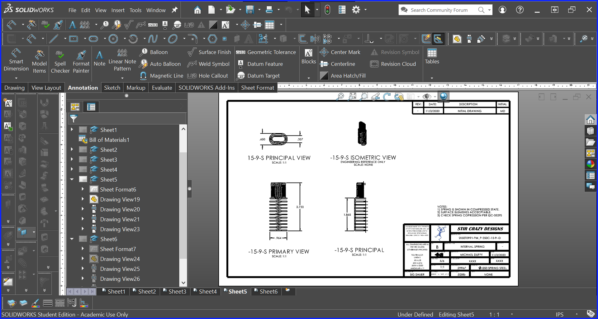
Internal Spring Drawing
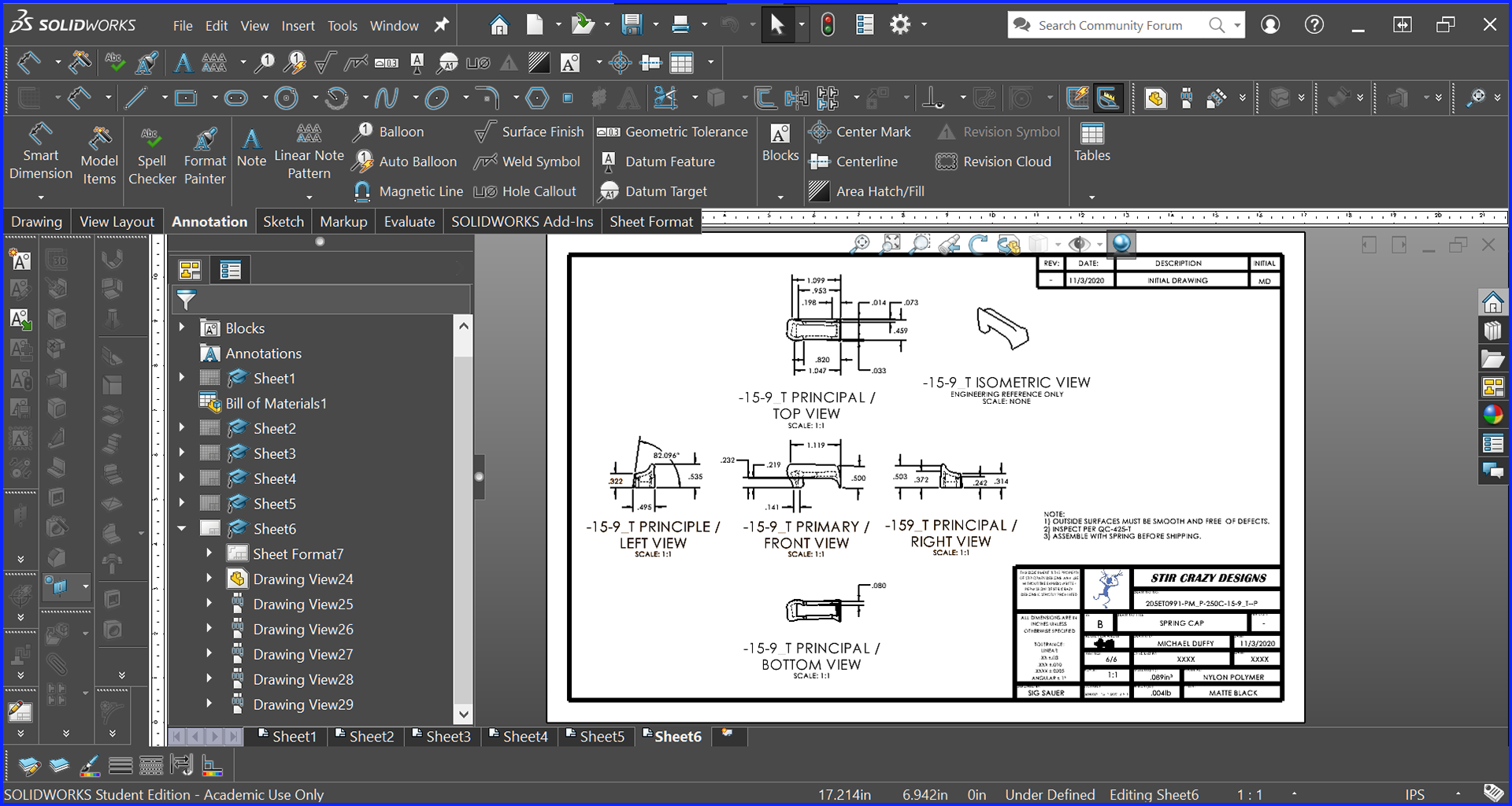
Upper Seat Drawing - Solidworks
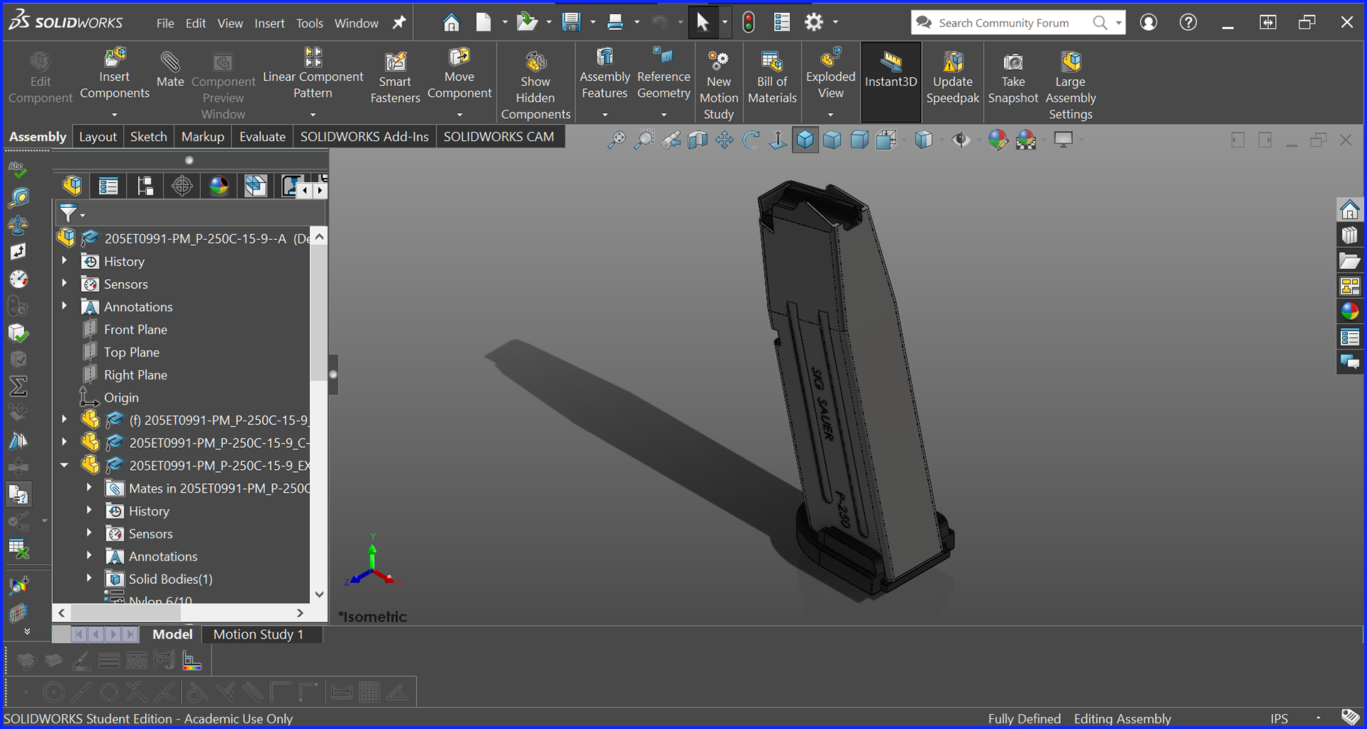
Assembly - Sig Sauer P-250 Magazine - Solidworks
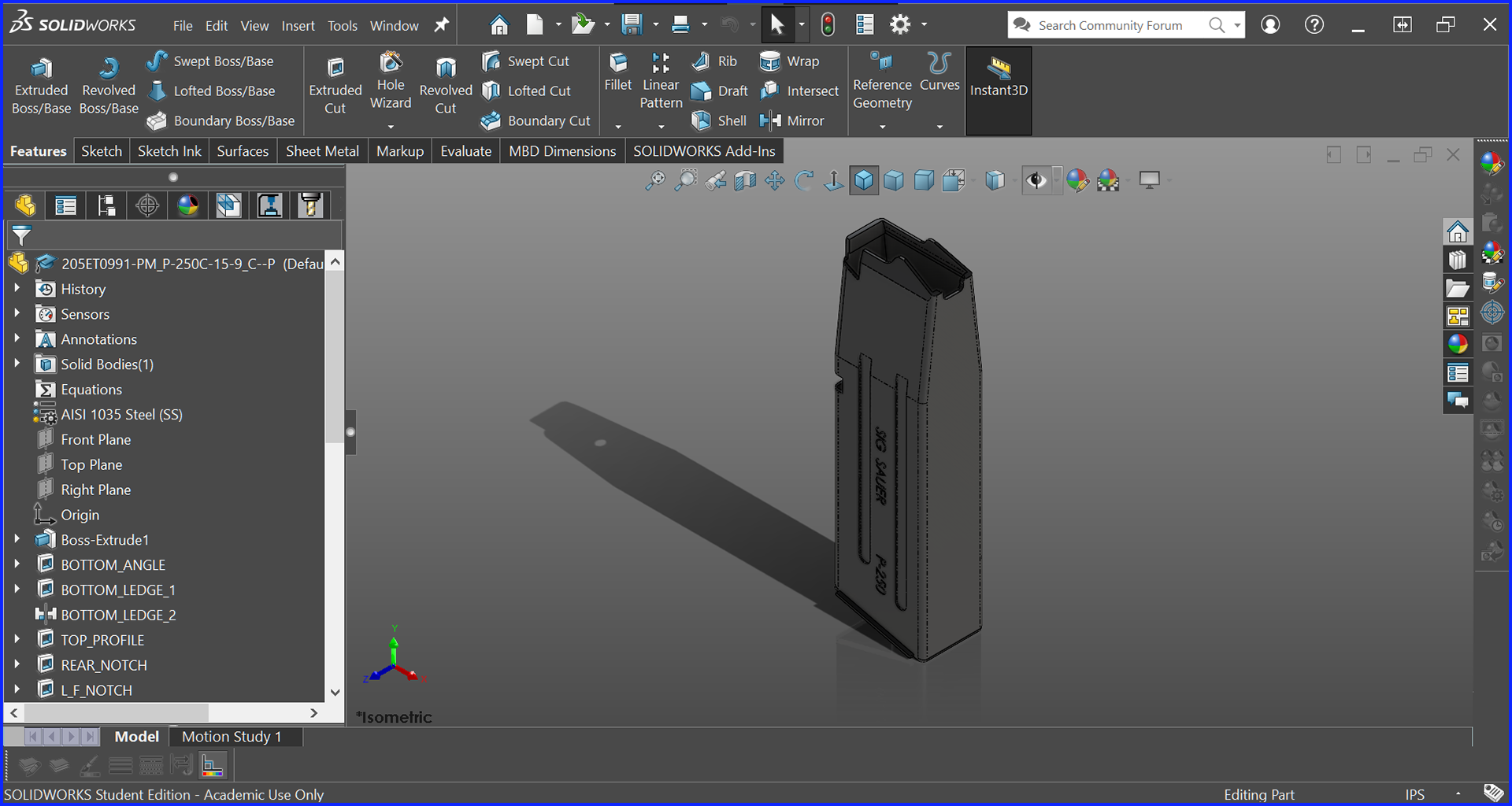
Magazine Shell
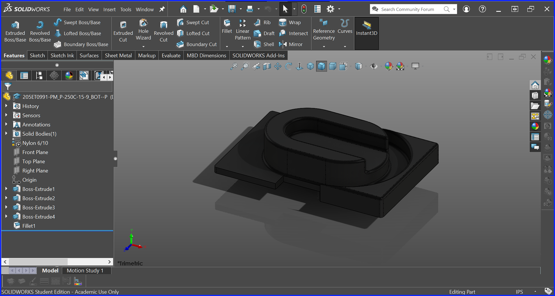
Spring Base
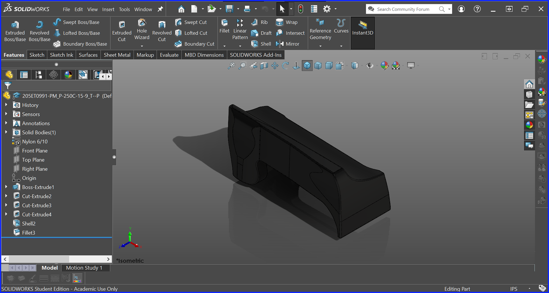
Upper Seat
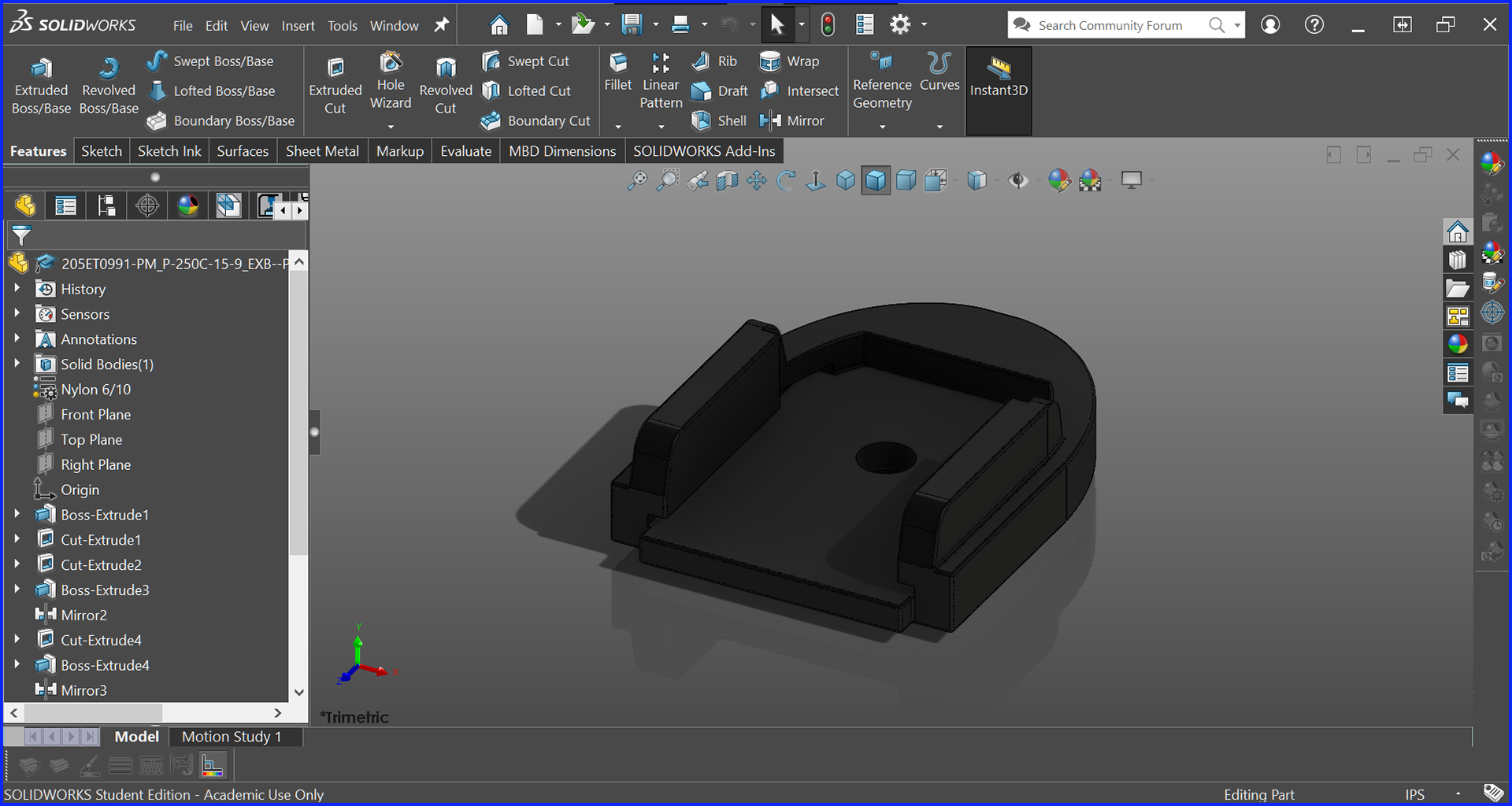
Base Plate
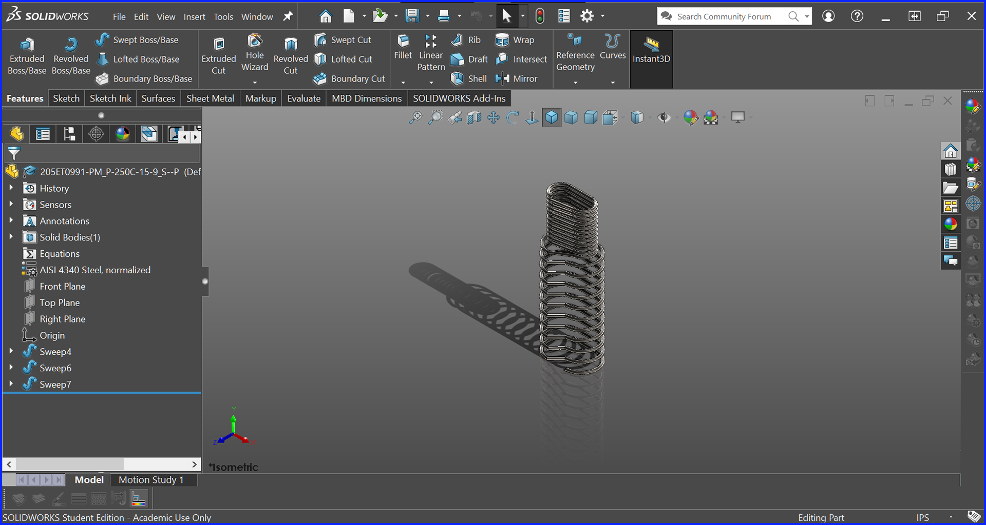
Internal Spring
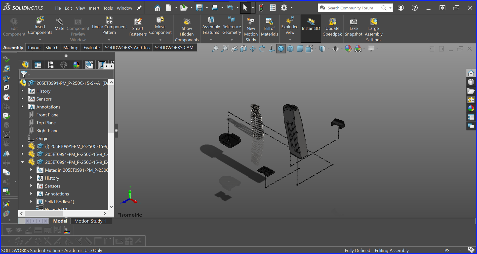
Exploded View
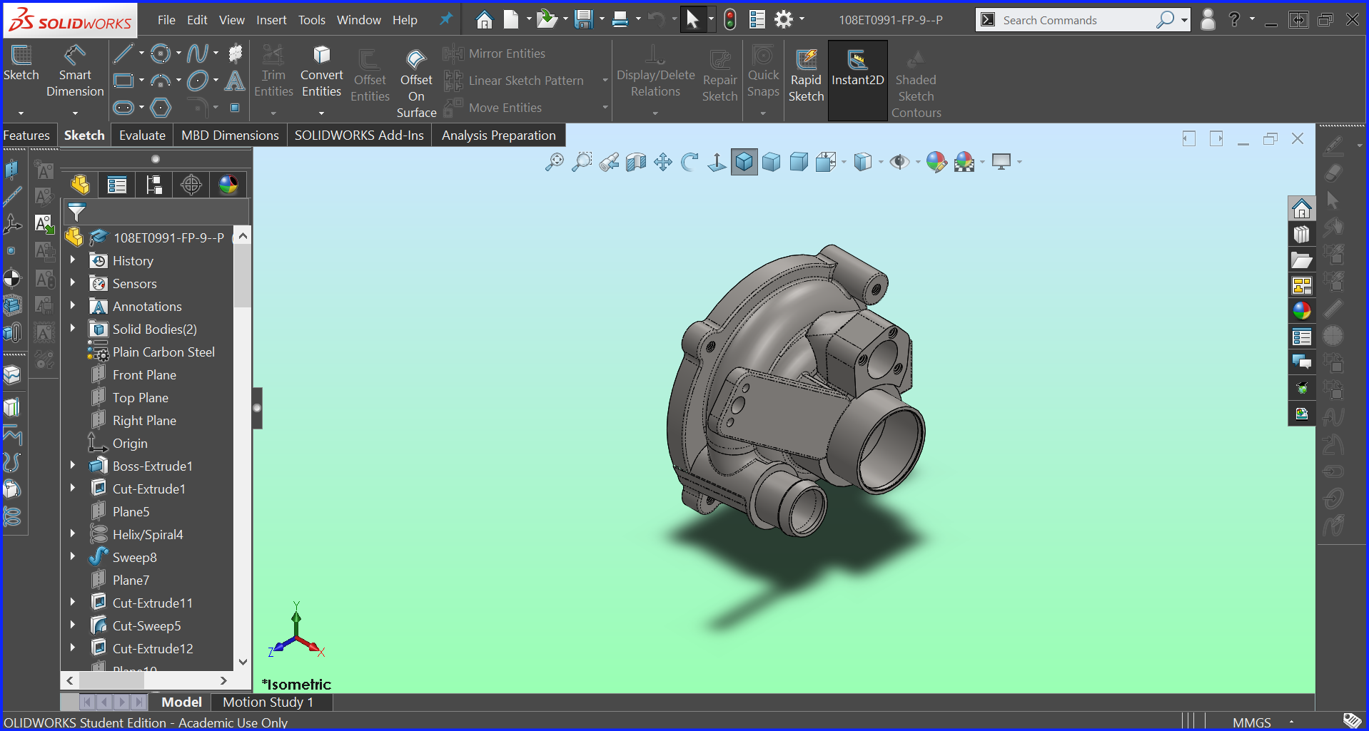
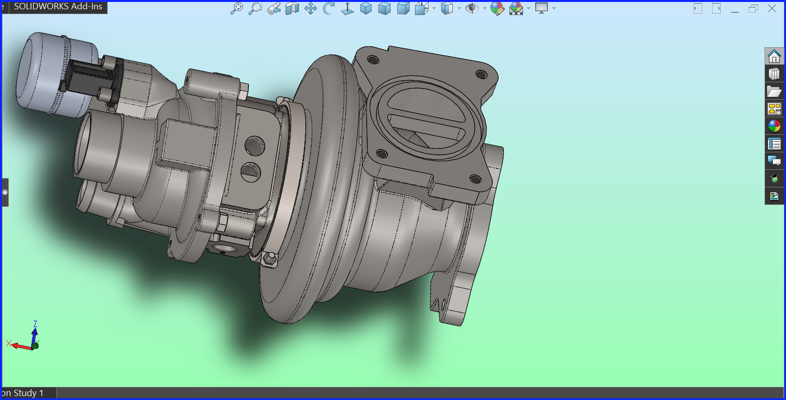
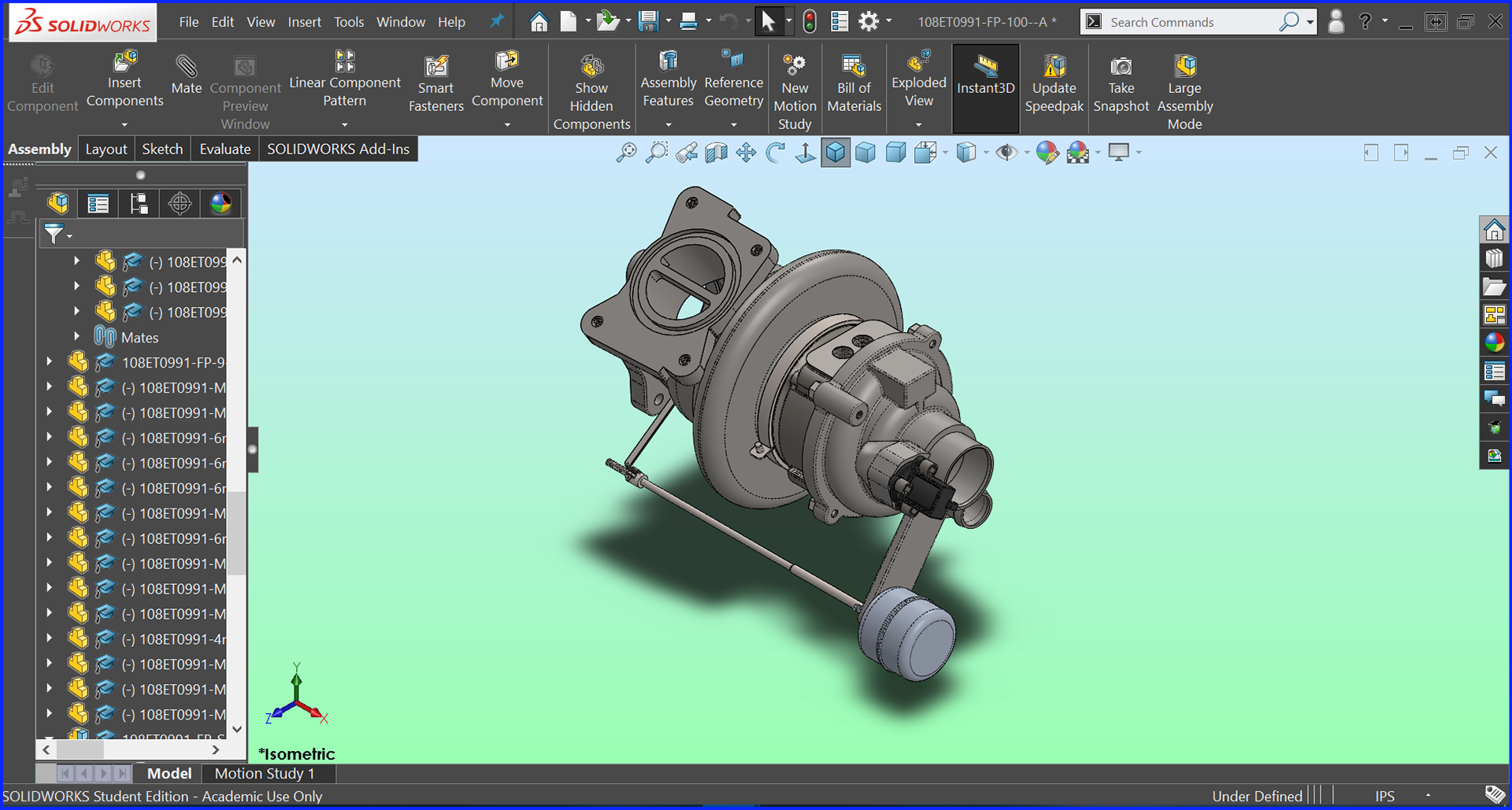
This set of pictures represents a turbocharger that I made for a student project for my first Solidworks Class.
Looking at it now, I can see many things that I would do differently now, but It is still pretty good for where I was at in my education, and shows how far I have come since.
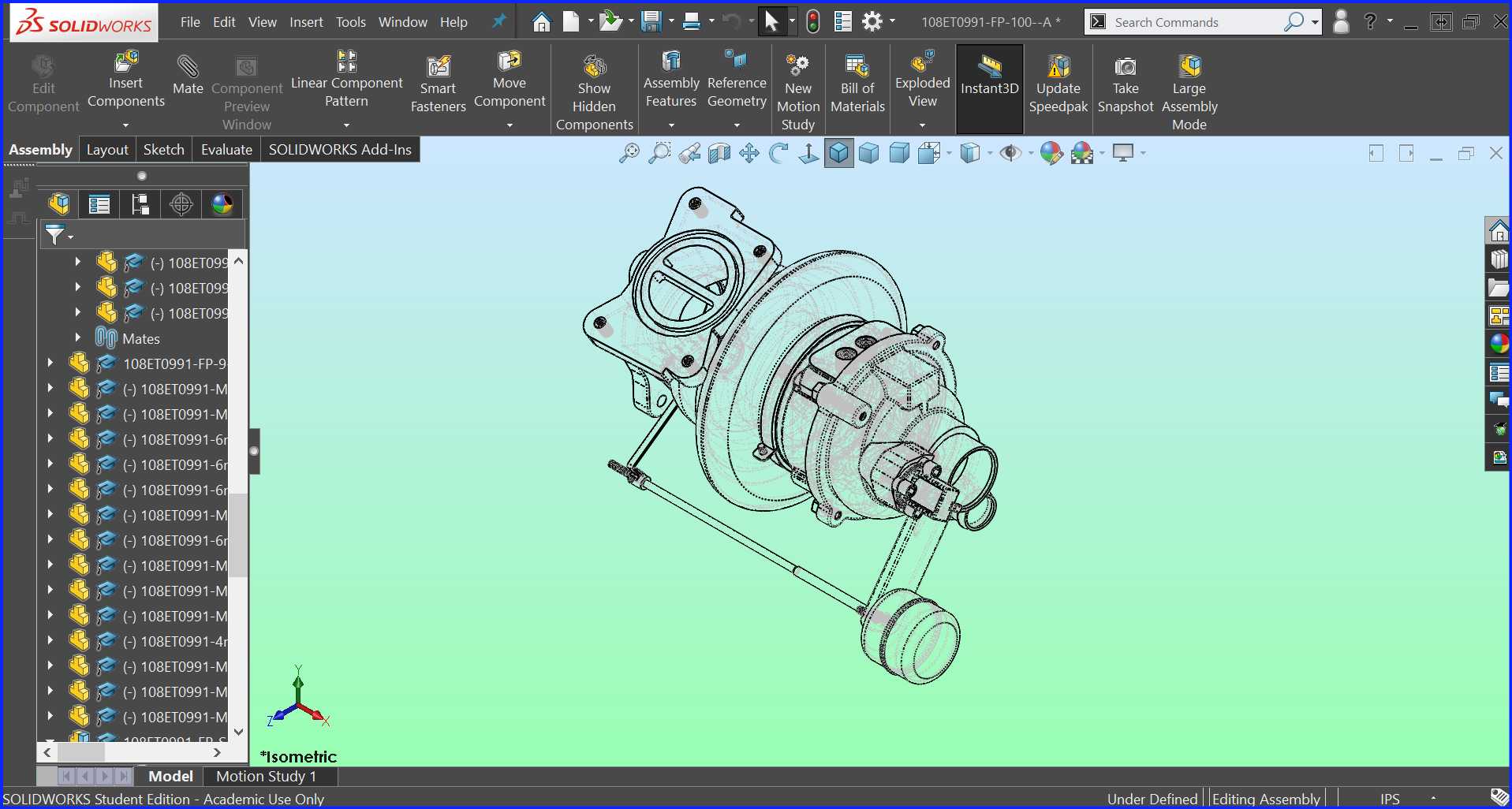
Turbocharger Assembly - Solidworks
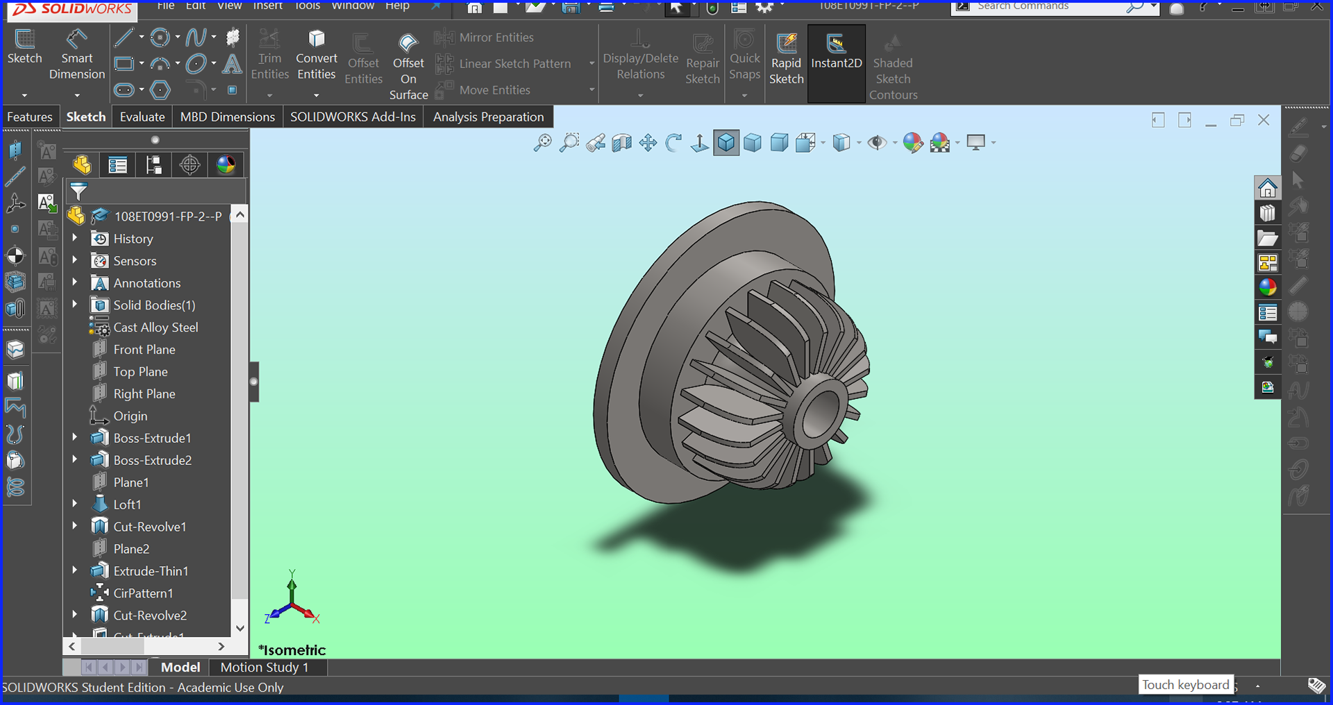
Basic Turbine
Compressor Housing
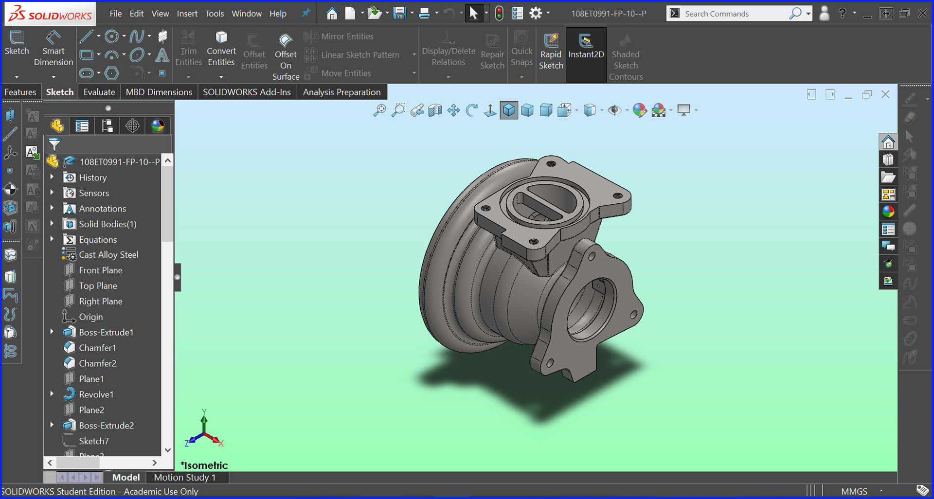
Exhaust Housing
View of Bottom
View of Manifold Connection Surface
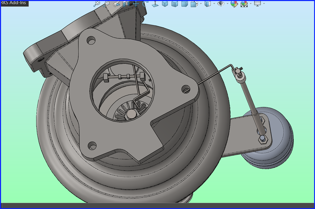
View of Exhaust Housing Showing Turbine and Wastegate Inside
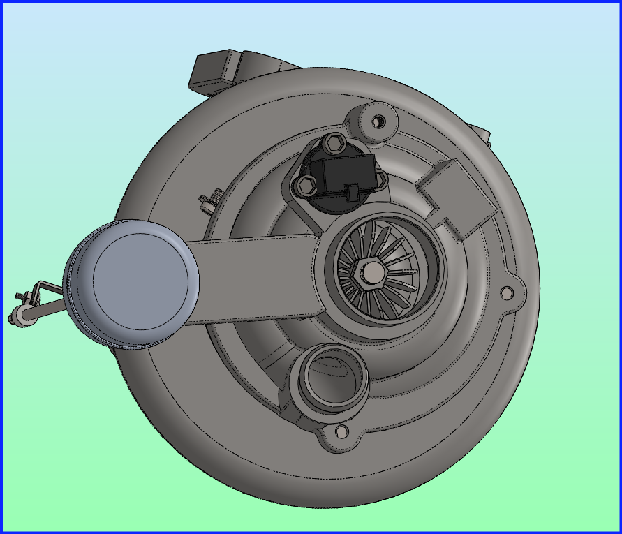
View of Compressor
Alt. View
Isometric View
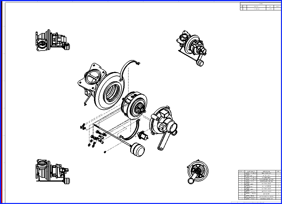
Drawing with Exploded View - Solidworks
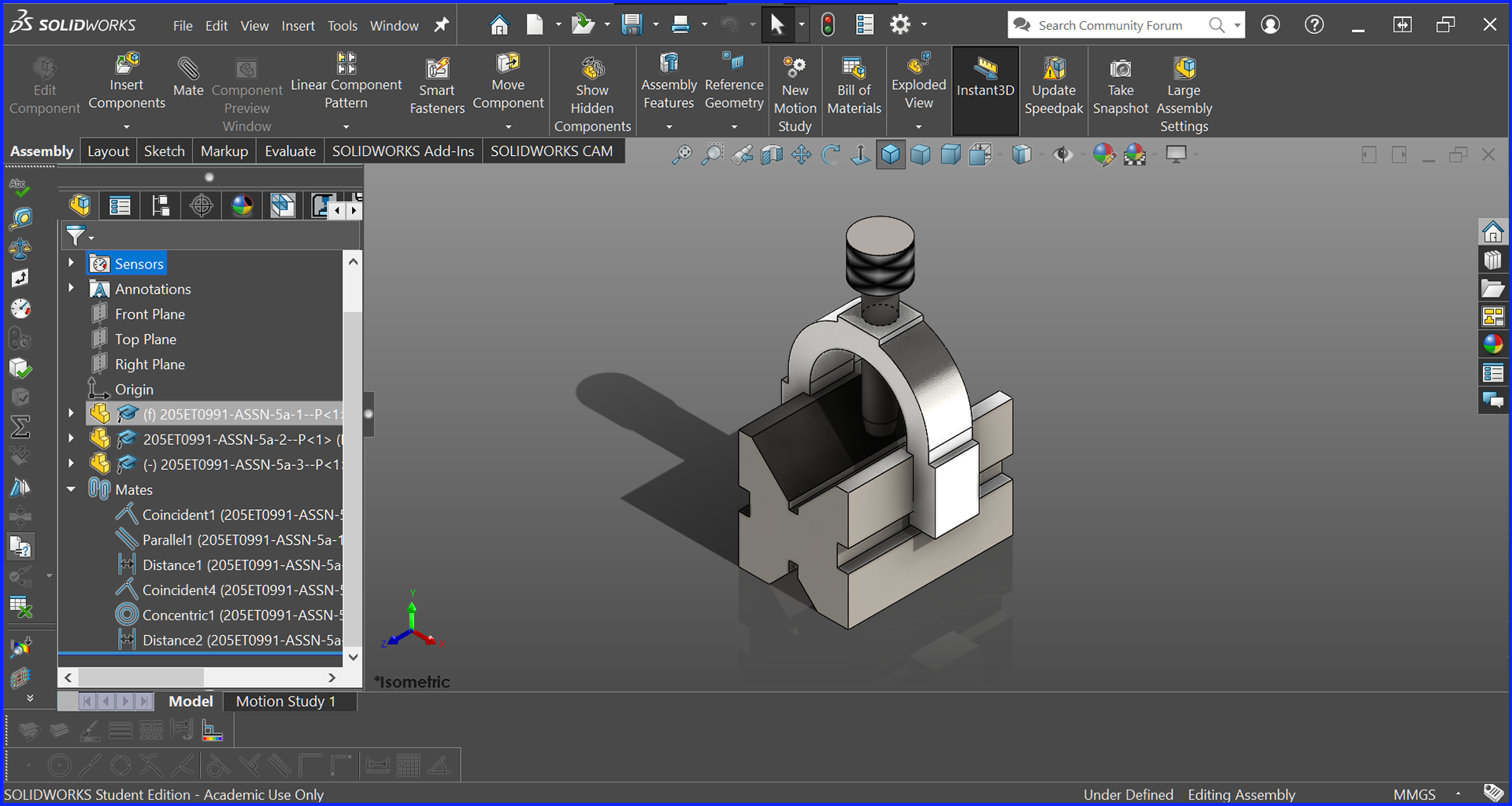
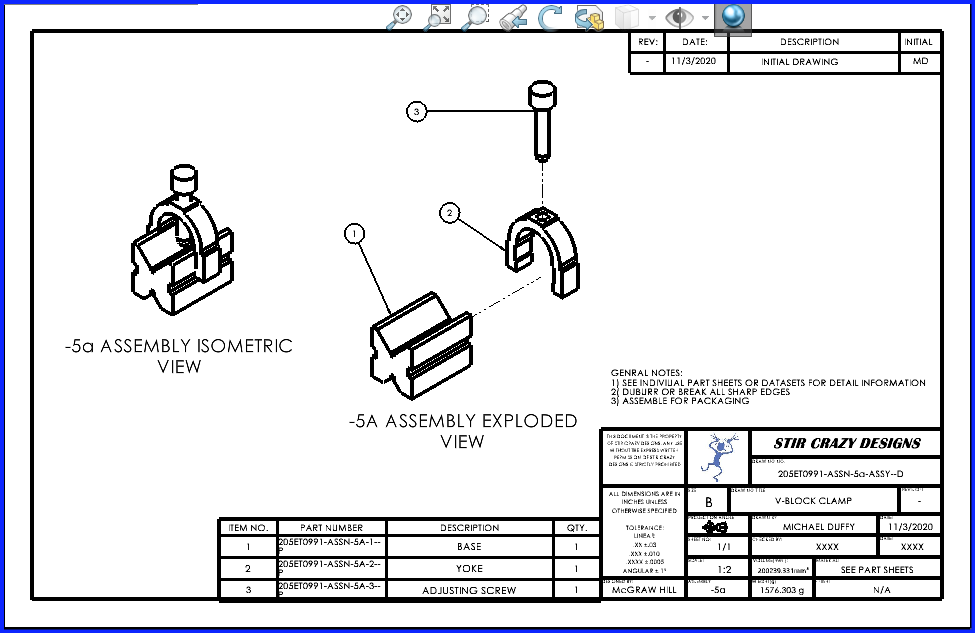
Small Clamp Assembly - Solidworks
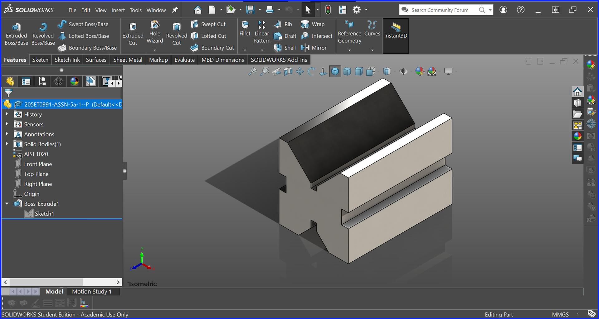
Base Block
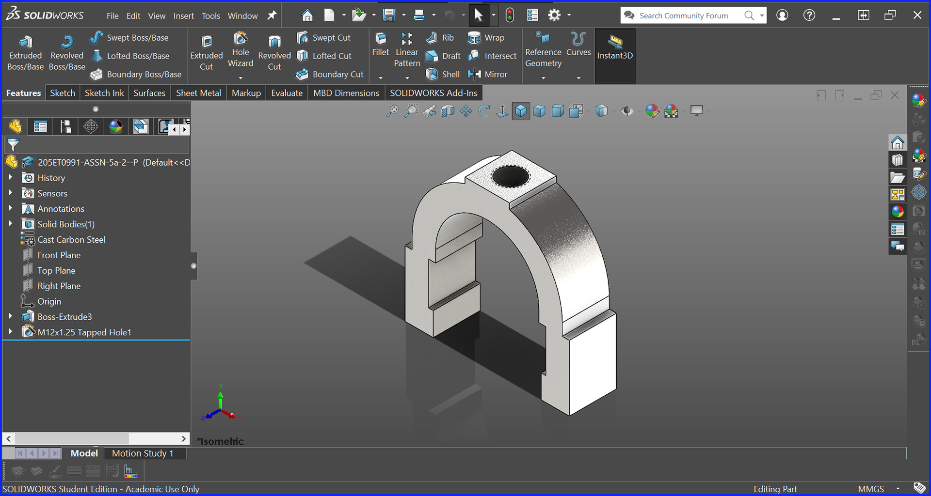
Bracket with Threaded Hole
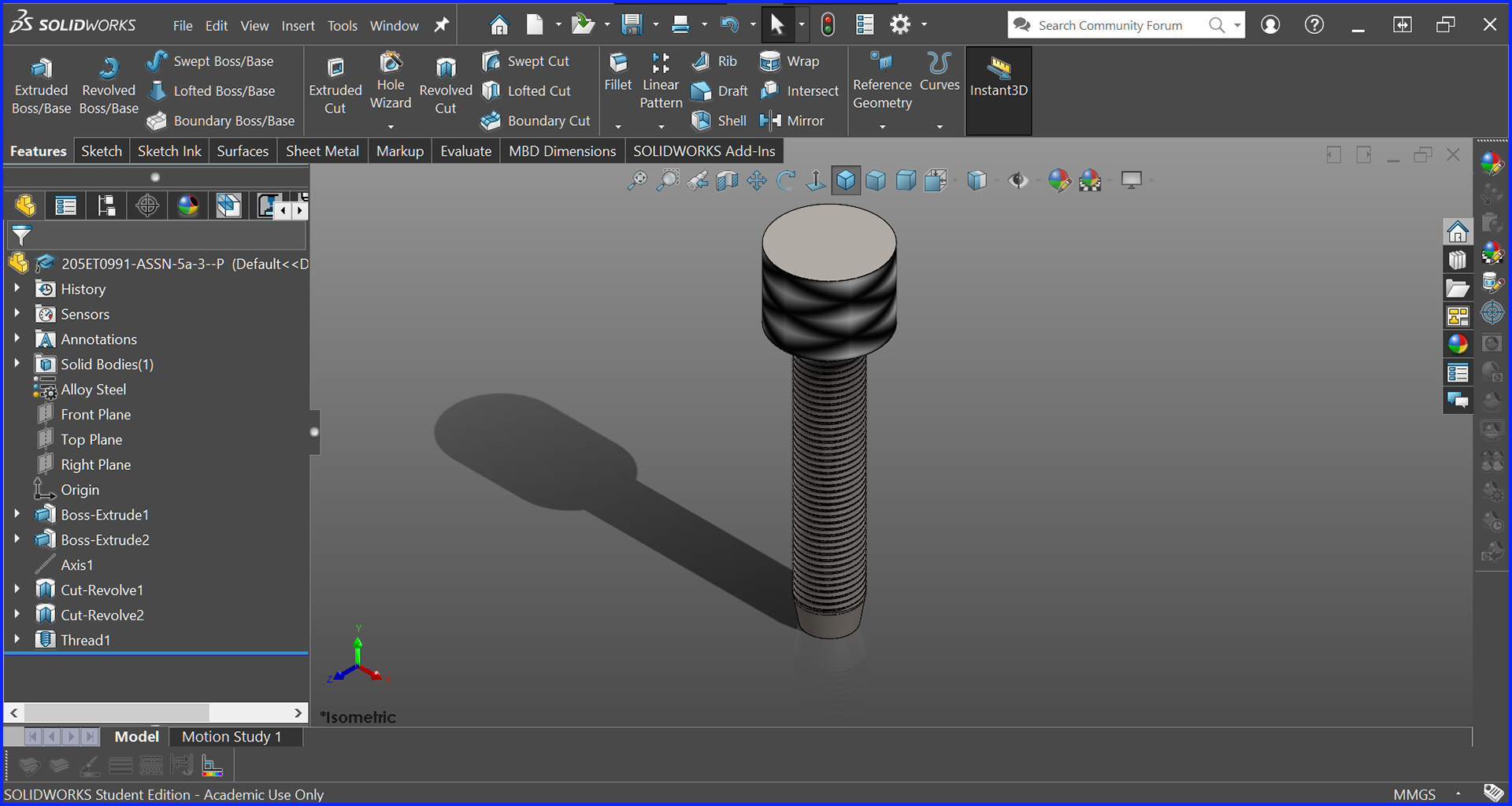
Main Screw with Knurling and Threads